
Elements Of Electromagnetics
7th Edition
ISBN: 9780190698614
Author: Sadiku, Matthew N. O.
Publisher: Oxford University Press
expand_more
expand_more
format_list_bulleted
Related questions
Concept explainers
Question
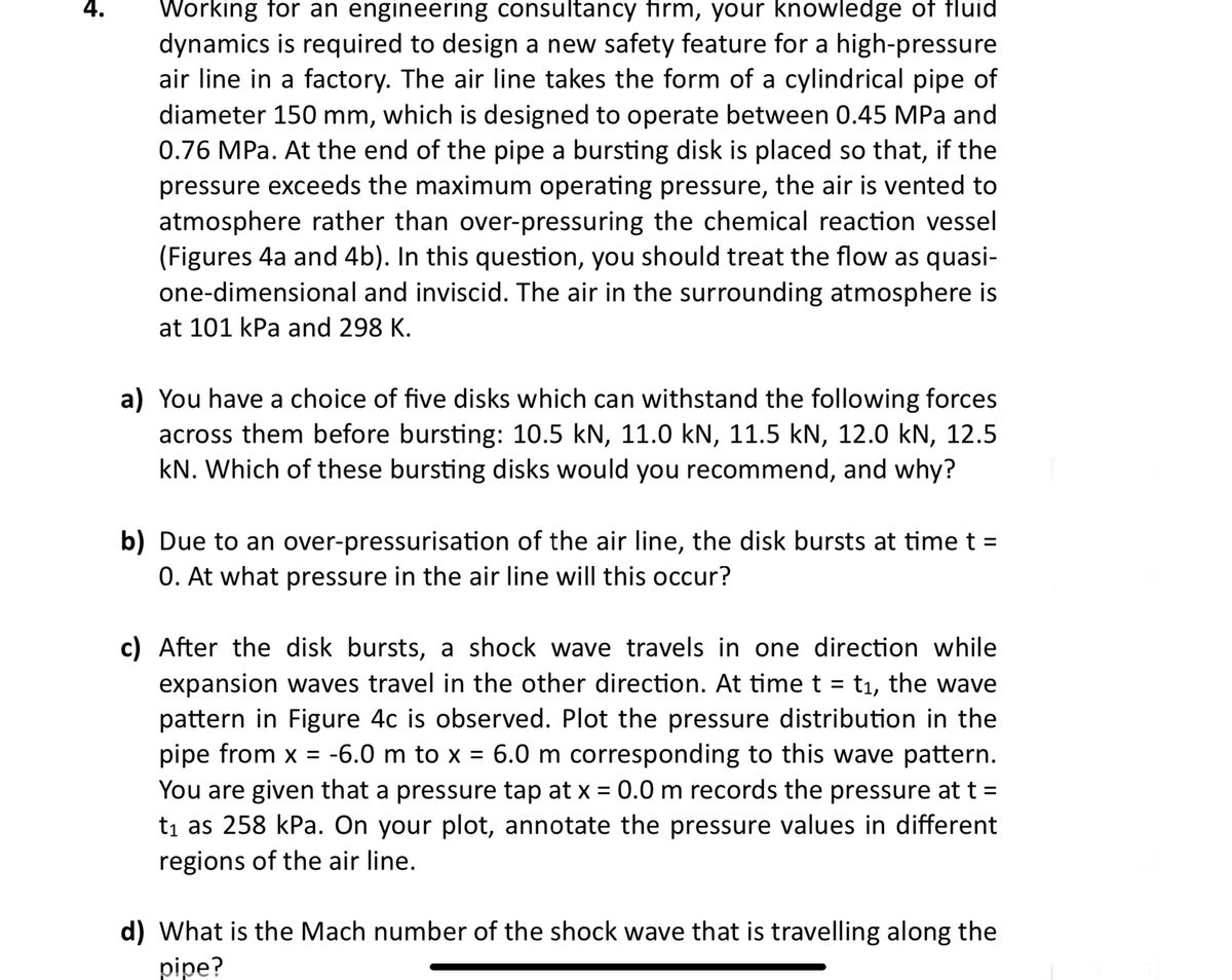

Transcribed Image Text:Working for an engineering consultancy firm, your knowledge of fluid
dynamics is required to design a new safety feature for a high-pressure
air line in a factory. The air line takes the form of a cylindrical pipe of
diameter 150 mm, which is designed to operate between 0.45 MPa and
0.76 MPa. At the end of the pipe a bursting disk is placed so that, if the
pressure exceeds the maximum operating pressure, the air is vented to
atmosphere rather than over-pressuring the chemical reaction vessel
(Figures 4a and 4b). In this question, you should treat the flow as quasi-
one-dimensional and inviscid. The air in the surrounding atmosphere is
at 101 kPa and 298 K.
a) You have a choice of five disks which can withstand the following forces
across them before bursting: 10.5 kN, 11.0 kN, 11.5 kN, 12.0 kN, 12.5
kN. Which of these bursting disks would you recommend, and why?
b) Due to an over-pressurisation of the air line, the disk bursts at time t =
0. At what pressure in the air line will this occur?
c) After the disk bursts, a shock wave travels in one direction while
expansion waves travel in the other direction. At time t = t₁, the wave
pattern in Figure 4c is observed. Plot the pressure distribution in the
pipe from x = -6.0 m to x = 6.0 m corresponding to this wave pattern.
You are given that a pressure tap at x = 0.0 m records the pressure at t =
t₁ as 258 kPa. On your plot, annotate the pressure values in different
regions of the air line.
d) What is the Mach number of the shock wave that is travelling along the
pipe?

Transcribed Image Text:aj
You have a cridice of five disks which can withstand the following forces
across them before bursting: 10.5 kN, 11.0 kN, 11.5 kN, 12.0 kN, 12.5
kN. Which of these bursting disks would you recommend, and why?
b) Due to an over-pressurisation of the air line, the disk bursts at time t =
0. At what pressure in the air line will this occur?
c) After the disk bursts, a shock wave travels in one direction while
expansion waves travel in the other direction. At time t = t₁, the wave
pattern in Figure 4c is observed. Plot the pressure distribution in the
pipe from x = -6.0 m to x = 6.0 m corresponding to this wave pattern.
You are given that a pressure tap at x = 0.0 m records the pressure at t =
t₁ as 258 kPa. On your plot, annotate the pressure values in different
regions of the air line.
d) What is the Mach number of the shock wave that is travelling along the
pipe?
e) In the frame of reference of the shock, what is the post-shock Mach
number? Also determine the post-shock temperature and explain
concisely in physical terms why the temperature has increased or
decreased through the shock.
f) Determine the value of t₁, i.e. how long after the disk burst was the
snapshot in Figure 4c captured?
Expert Solution
This question has been solved!
Explore an expertly crafted, step-by-step solution for a thorough understanding of key concepts.

Step by stepSolved in 4 steps with 3 images

Knowledge Booster


Learn more about
Need a deep-dive on the concept behind this application? Look no further. Learn more about this topic, mechanical-engineering and related others by exploring similar questions and additional content below.Similar questions
- Read the question carefully and give me right solution according to the question. Note: carefully answer with part Barrow_forwardThe working fluid of the pressure gauge in Fig. 157 is mercury. Estimate the volumetric flow rate in the tube if the fluid flowing through it is (a) gasoline and (b) nitrogen, at 20 ° C and 1 atmarrow_forwardYour team is designing a chemical processing plant. You are the liquid handling and transportation specialist, and you need to transport a solvent (μ = 3.1 cP, ρ = 122k kg/m3) from a storage tank to a reaction vessel. Due to other equipment constraints, the fluid velocity must be 0.8 m/sec, and you must use stainless steel piping (ε = 0.00015 mm) with a total length (L) of 12 m. Determine the pipe inner diameter (ID) you will need to achieve a pressure drop of 0.3 kPa. Use the Moody chart.arrow_forward
- (cc) BY-NO-SA Niel Crews, 2013 An insulated, rigid vessel is initially empty (evacuated). However, it is connected to a steam line that is maintained at 200 psia and 500 °F. The valve is opened until the flow into the tank slows and stops (which occurs when the pressure in the tank is equal to the pressure in the steam line), at which point the valve is closed. What is the temperature within the vessel? °Farrow_forwardsolve it fastarrow_forwardEngine oil (n = 0.20 Pa·s) passes through a fine 2.00-mm-diameter tube that is 10.2 cm long. ▼ Part A What pressure difference is needed to maintain a flow rate of 4.4 mL/min ? Express your answer to two significant figures and include the appropriate units. ΔΡ = 4.76 Submit μA Provide Feedback Pa Previous Answers Request Answer ? X Incorrect; Try Again; 27 attempts remaining Next >arrow_forward
- Don't provide the wrong solution, Humble request.arrow_forwardAs shown in Fig. 4.33, the pipe diameter is d = 25 mm. l1 = 8 m; l2 = 1 m;H = 5 m. The nozzle diameter is d0 = 10 mm, and the minor loss coefficientsof inlet and elbow are f1 = 0.5 and f2 = 0.1 respectively. For nozzle, f3 =0.1 (relative to the outflow velocity of nozzle). The friction factor is k = 0:03.Try to determine jet height h.arrow_forward3. A pump steadily circulates oil used for lubricating heavy machine tools. The volume flow rate and temperature of the oil are 300 gal/min and 104°F, respectively. At 104°F, the kinematic viscosity and the specific gravity of the oil are 2.15 x 10⁻³ ft² /s and 0.89, respectively. The pipe lengths are 25 ft for the 4-in diameter pipe and 75 ft for the 3-in diameter one. The Schedule-40 steel pipe has an average roughness element size of 0.0018 in. If all minor losses can be ignored, evaluate how much power (in a unit of horsepower) the pump delivers to the oil. 6 ft 22 ft Flow 15 ft Discharge line 3-in Schedule 40 Suction line 4-in Schedule 40 steel pipe steel pipe Pumparrow_forward
arrow_back_ios
SEE MORE QUESTIONS
arrow_forward_ios
Recommended textbooks for you
- Elements Of ElectromagneticsMechanical EngineeringISBN:9780190698614Author:Sadiku, Matthew N. O.Publisher:Oxford University Press
 Mechanics of Materials (10th Edition)Mechanical EngineeringISBN:9780134319650Author:Russell C. HibbelerPublisher:PEARSON
 Thermodynamics: An Engineering ApproachMechanical EngineeringISBN:9781259822674Author:Yunus A. Cengel Dr., Michael A. BolesPublisher:McGraw-Hill Education
  Control Systems EngineeringMechanical EngineeringISBN:9781118170519Author:Norman S. NisePublisher:WILEY
 Mechanics of Materials (MindTap Course List)Mechanical EngineeringISBN:9781337093347Author:Barry J. Goodno, James M. GerePublisher:Cengage Learning
 Engineering Mechanics: StaticsMechanical EngineeringISBN:9781118807330Author:James L. Meriam, L. G. Kraige, J. N. BoltonPublisher:WILEY
Elements Of Electromagnetics
Mechanical Engineering
ISBN:9780190698614
Author:Sadiku, Matthew N. O.
Publisher:Oxford University Press
Mechanics of Materials (10th Edition)
Mechanical Engineering
ISBN:9780134319650
Author:Russell C. Hibbeler
Publisher:PEARSON
Thermodynamics: An Engineering Approach
Mechanical Engineering
ISBN:9781259822674
Author:Yunus A. Cengel Dr., Michael A. Boles
Publisher:McGraw-Hill Education
Control Systems Engineering
Mechanical Engineering
ISBN:9781118170519
Author:Norman S. Nise
Publisher:WILEY
Mechanics of Materials (MindTap Course List)
Mechanical Engineering
ISBN:9781337093347
Author:Barry J. Goodno, James M. Gere
Publisher:Cengage Learning
Engineering Mechanics: Statics
Mechanical Engineering
ISBN:9781118807330
Author:James L. Meriam, L. G. Kraige, J. N. Bolton
Publisher:WILEY