Elements Of Electromagnetics
7th Edition
ISBN: 9780190698614
Author: Sadiku, Matthew N. O.
Publisher: Oxford University Press
expand_more
expand_more
format_list_bulleted
Concept explainers
Question
thumb_up100%
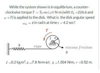
While the system shown is in equilibrium, a counter-clockwise torque T =T0sin(ωt) N-m(with T0 = 226.6 and ω=7) is applied to teh disk. What is the disk angular speed ω0 = ? in rad/s at time t = 4.2 sec? ( I = 0.2 kg.m2, b = 7.8 N-m-s/r, k = 1,504 N/m, r = 0.52m )

Transcribed Image Text:While the system shown is in equilibrium, a counter-
clockwise torque T = To sin (wt) N-m (with To =226.6 and
w =7) is applied to the disk. What is the disk angular speed
wm = 0 in rad/s at time t = 4.2 sec?
T
k
rope
viscous friction
b
I =0.2 kg.m?, 6 =7.8 N-m-s/r, k =1,504 N/m, r =0.52 m.
Expert Solution
This question has been solved!
Explore an expertly crafted, step-by-step solution for a thorough understanding of key concepts.
This is a popular solution
Trending nowThis is a popular solution!
Step by stepSolved in 2 steps with 3 images

Knowledge Booster
Learn more about
Need a deep-dive on the concept behind this application? Look no further. Learn more about this topic, mechanical-engineering and related others by exploring similar questions and additional content below.Similar questions
- draw a free body diagram and kinetic diagramarrow_forwardWng Consider systems A and B shown in the figure. The ratio of natural frequency of system A(wn,) to natural frequency of system B(wng), i.e. 4 is: (for the disc, assume moment of inertia about its centre is Assume g = 9.81 m/s? juiny m m. g = 9.81 m/s? A a frictionless No slip V3 о ООО оarrow_forwardThe system below shows a system consisting of 4 masses that are turn. If R₁= R₂ = R3 = R4 = RA = RB = 10, determine the MA and MB placed in field A and field B.arrow_forward
- A motor (which is not shown in the figure) rotates the rod OB about the z-axis. The torque applied by the motor is given as T = 0.4 Nm. The rod OB is rotating at 3 rad/s at that instant which R = 0.4 m. And a rope attached to the slider A is let out at the constant rate of 0.25 m/s. What is the angular velocity after 10s?(Please neglect the mass of rod OB).arrow_forward4а. Show that the torque t = la, where I is the rotational inertia. Consider the pulley system shown in figure 4. Suppose the pulley is made up of a disc with mass Ma and a ring (hoop) with mass M, as shown in Figure 4a. Find the moment of inertia I, of the pulley through the center of mass. 4b. Find the angular acceleration a, of the pulley as a function of Ip, 0, M1, M2, µk. You may assume that there is no slipping between the pulley and the rope and the mass of the rope is negligibly small in comparison with the mass M1, and M2. The coefficient of friction between M2 and the incline is µk with M1> M2. 4c. Mr md MK outer ving (Mr) Central dise (Ma) RI axis at RAzti on X- Sedi on a pullagarrow_forwardA wheel in fixed axis rotation spins at 300 rpm and decelerates at α = 3 rad/s2. How long does it take for the wheel to come to a complete stop?arrow_forward
- Consider the disk and axle shown below. The axle has a constant angular velocity (in rad/s) in the inertial frame given by: A/N = 0.152 i. The disk has an angular velocity (in rad/s) in the axle frame given by: p/A 0.504 k . Calculate the magnitude of angular acceleration of the disk in the inertial frame (in rad/s?). N Darrow_forwardfinished in an analytical wayarrow_forward
arrow_back_ios
arrow_forward_ios
Recommended textbooks for you
 Elements Of ElectromagneticsMechanical EngineeringISBN:9780190698614Author:Sadiku, Matthew N. O.Publisher:Oxford University Press
 Mechanics of Materials (10th Edition)Mechanical EngineeringISBN:9780134319650Author:Russell C. HibbelerPublisher:PEARSON
 Thermodynamics: An Engineering ApproachMechanical EngineeringISBN:9781259822674Author:Yunus A. Cengel Dr., Michael A. BolesPublisher:McGraw-Hill Education
 Control Systems EngineeringMechanical EngineeringISBN:9781118170519Author:Norman S. NisePublisher:WILEY
 Mechanics of Materials (MindTap Course List)Mechanical EngineeringISBN:9781337093347Author:Barry J. Goodno, James M. GerePublisher:Cengage Learning
 Engineering Mechanics: StaticsMechanical EngineeringISBN:9781118807330Author:James L. Meriam, L. G. Kraige, J. N. BoltonPublisher:WILEY

Elements Of Electromagnetics
Mechanical Engineering
ISBN:9780190698614
Author:Sadiku, Matthew N. O.
Publisher:Oxford University Press

Mechanics of Materials (10th Edition)
Mechanical Engineering
ISBN:9780134319650
Author:Russell C. Hibbeler
Publisher:PEARSON

Thermodynamics: An Engineering Approach
Mechanical Engineering
ISBN:9781259822674
Author:Yunus A. Cengel Dr., Michael A. Boles
Publisher:McGraw-Hill Education

Control Systems Engineering
Mechanical Engineering
ISBN:9781118170519
Author:Norman S. Nise
Publisher:WILEY

Mechanics of Materials (MindTap Course List)
Mechanical Engineering
ISBN:9781337093347
Author:Barry J. Goodno, James M. Gere
Publisher:Cengage Learning

Engineering Mechanics: Statics
Mechanical Engineering
ISBN:9781118807330
Author:James L. Meriam, L. G. Kraige, J. N. Bolton
Publisher:WILEY