
Elements Of Electromagnetics
7th Edition
ISBN: 9780190698614
Author: Sadiku, Matthew N. O.
Publisher: Oxford University Press
expand_more
expand_more
format_list_bulleted
Related questions
Concept explainers
Question
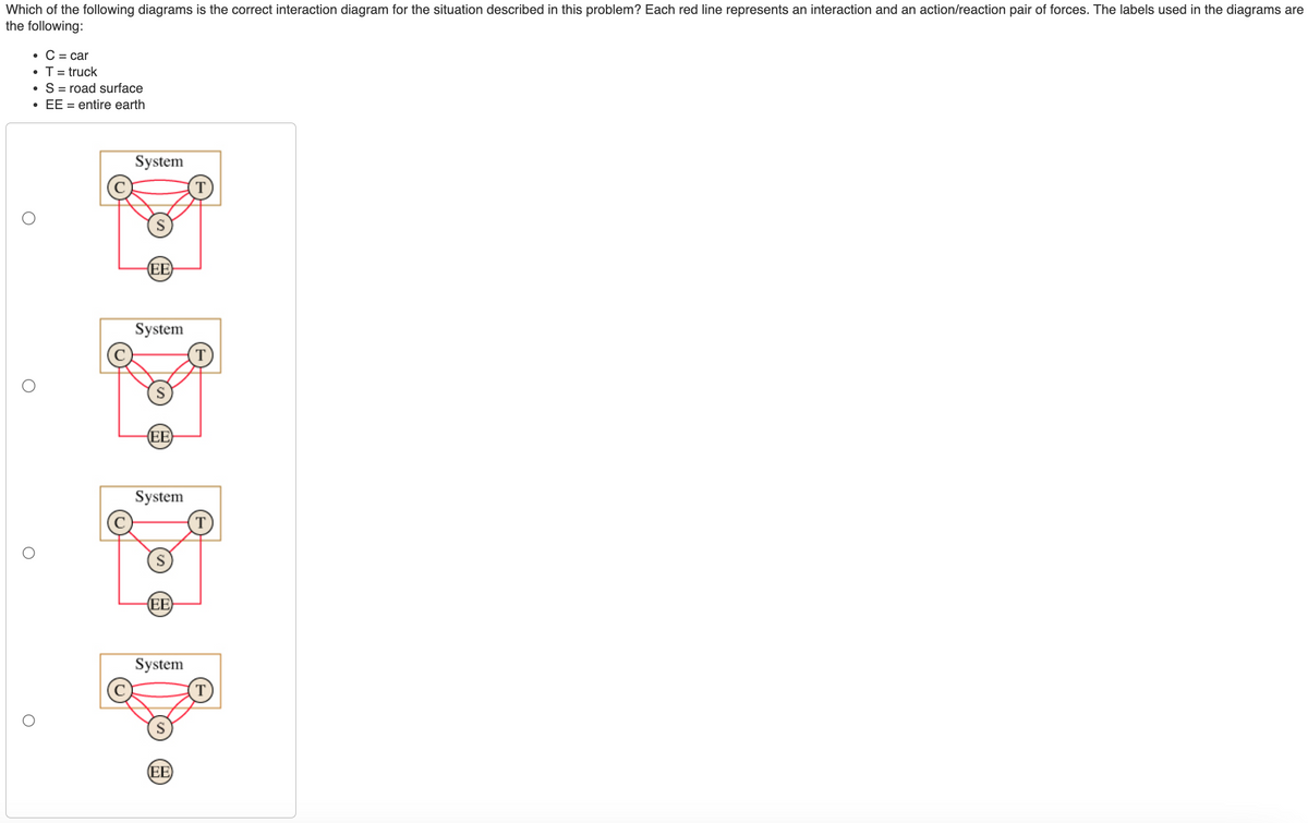

Transcribed Image Text:Which of the following diagrams is the correct interaction diagram for the situation described in this problem? Each red line represents an interaction and an action/reaction pair of forces. The labels used in the diagrams are
the following:
• C = car
●
O
O
T = truck
S = road surface
EE = entire earth
System
(EE)
System
(EE)
System
(EE)
System
(EE)

Transcribed Image Text:Learning Goal:
A 1290 -kg car is pushing an out-of-gear 2200 -kg truck that has a dead battery.
When the driver steps on the accelerator, the drive wheels of the car push
horizontally against the ground with a force of 4580 N. The rolling friction of the car
can be neglected, but the heavier truck has a rolling friction of 755 N, including the
"friction" of turning the truck's drivetrain. What is the magnitude of the force the car
applies to the truck?
PROBLEM-SOLVING STRATEGY 7.1 Interacting-objects problems
MODEL: Identify which objects are part of the system and which are part of the environment. Make simplifying assumptions.
VISUALIZE: Draw a pictorial representation.
▪ Show important points in the motion with a sketch. You may want to give each object a separate coordinate system. Define symbols, list acceleration constraints, and identify what the
problem is trying to find.
▪ Draw an interaction diagram to identify the forces on each object and all action/reaction pairs.
▪ Draw a separate free-body diagram for each object showing only the forces acting on that object, not forces exerted by the object. Connect the force vectors of action/reaction pairs with
dashed lines.
SOLVE: Use Newton's second and third laws.
▪ Write the equations of Newton's second law for each object, using the force information from the free-body diagrams.
Equate the magnitudes of action/reaction pairs.
■
▪ Include the acceleration constraints, the friction model, and other quantitative information relevant to the problem.
▪ Solve for the acceleration, and then use kinematics to find velocities and positions.
REVIEW: Check that your result has the correct units and significant figures, is reasonable, and answers the question.
Model
The car and the truck are separate objects that form the system. Since only the straight-line motion of the car and truck
surface are part of the environment.
involved in this problem, model them as particles. The earth and the road
Expert Solution
This question has been solved!
Explore an expertly crafted, step-by-step solution for a thorough understanding of key concepts.

This is a popular solution

Trending nowThis is a popular solution!

Step by stepSolved in 3 steps with 2 images

Knowledge Booster


Learn more about
Need a deep-dive on the concept behind this application? Look no further. Learn more about this topic, mechanical-engineering and related others by exploring similar questions and additional content below.Similar questions
- Newton’s 2nd Law Lab (Modeling friendly lab) Go to the PhET simulation Forces & Motion. https://phet.colorado.edu/sims/html/forcesandmotionbasics/latest/forcesandmotionbasics_en.html Select “Acceleration” Click to show Forces, Sum of Forces, Values, Mass, and Acceleration. There are two experiments for this activity – make sure you include both. Experiment #1: Acceleration vs. Force In this lab you will determine the relationship between acceleration and net force. Choose a mass at the beginning, and keep it constant for this entire experiment. Set the friction to zero. This will make your Applied Force equal to the net force. Record data for five different values of Applied Force. Graph Acceleration vs. Net Force. Graph this in Google sheets(you want a line graph - it should only have one line). Make sure that Applied Force information is used as the x value Make sure that Acceleration information is used as the y value Add a trendline – see what fits best –…arrow_forwardI am attaching both questions for 4 and 5 with the question in the image. thank you. NOTE : So the last person answered this question WITHOUT refencing the answer for whether question 4 or 5 answeres were given, so i am asking for question 5(or the answer for the question that was NOT solved because it was not referenced.) These were the following answers given to me from the last person on bartleby who answered my question without referencing whether it was the answer for question 4 or 5. 1 pass 2 fail 3 fail 4 passarrow_forwardLooking for a handwritten solution with a simple FBD. [Warning: Do not provide typed solution ,Only handwritten allowed]arrow_forward
- The following shows the top view of the partially open doors on one side of an entertainment center cabinet. The wooden doors are hinged to each other and one door is hinged to the cabinet. There is also a ternary, metal link attached to the cabinet and door through pin joints. As spring- loaded piston-in-cylinder device attaches to the ternary link and the cabinet through pin joints. Draw a kinematic diagram of the door system and find the mobility of this mechanism. cylinder piston O cabinet link hinge door door hingearrow_forwardi have a couple of questions i need help witharrow_forwardThe entire top surface on the part below must be flat within 0.5 but each 25x25 patch must be flat within 0.1. Apply the necessary geometric controls to achieve this result. Please refer to the attached image.arrow_forward
- Need only a handwritten solution only (not a typed one).arrow_forwardA force of F is applied on the system at A as shown in the figure in order to maintain the system in equilibrium. ii) What are the magnitudes of the components of force F parallel and perpendicular to link AC?arrow_forwardHello Sir,Good Morning. I'm sorry Sir the previous question is incompleteI'll re-attach the following. The following below is my question . Please advice. Thank you. Regards,Irfanarrow_forward
arrow_back_ios
arrow_forward_ios
Recommended textbooks for you
- Elements Of ElectromagneticsMechanical EngineeringISBN:9780190698614Author:Sadiku, Matthew N. O.Publisher:Oxford University Press
 Mechanics of Materials (10th Edition)Mechanical EngineeringISBN:9780134319650Author:Russell C. HibbelerPublisher:PEARSON
 Thermodynamics: An Engineering ApproachMechanical EngineeringISBN:9781259822674Author:Yunus A. Cengel Dr., Michael A. BolesPublisher:McGraw-Hill Education
  Control Systems EngineeringMechanical EngineeringISBN:9781118170519Author:Norman S. NisePublisher:WILEY
 Mechanics of Materials (MindTap Course List)Mechanical EngineeringISBN:9781337093347Author:Barry J. Goodno, James M. GerePublisher:Cengage Learning
 Engineering Mechanics: StaticsMechanical EngineeringISBN:9781118807330Author:James L. Meriam, L. G. Kraige, J. N. BoltonPublisher:WILEY
Elements Of Electromagnetics
Mechanical Engineering
ISBN:9780190698614
Author:Sadiku, Matthew N. O.
Publisher:Oxford University Press
Mechanics of Materials (10th Edition)
Mechanical Engineering
ISBN:9780134319650
Author:Russell C. Hibbeler
Publisher:PEARSON
Thermodynamics: An Engineering Approach
Mechanical Engineering
ISBN:9781259822674
Author:Yunus A. Cengel Dr., Michael A. Boles
Publisher:McGraw-Hill Education
Control Systems Engineering
Mechanical Engineering
ISBN:9781118170519
Author:Norman S. Nise
Publisher:WILEY
Mechanics of Materials (MindTap Course List)
Mechanical Engineering
ISBN:9781337093347
Author:Barry J. Goodno, James M. Gere
Publisher:Cengage Learning
Engineering Mechanics: Statics
Mechanical Engineering
ISBN:9781118807330
Author:James L. Meriam, L. G. Kraige, J. N. Bolton
Publisher:WILEY