Introductory Circuit Analysis (13th Edition)
13th Edition
ISBN: 9780133923605
Author: Robert L. Boylestad
Publisher: PEARSON
expand_more
expand_more
format_list_bulleted
Concept explainers
Question

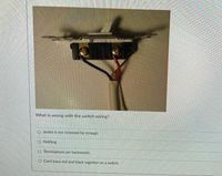
Transcribed Image Text:What is wrong with the switch wiring?
O Jacket is not removed far enough
O Nothing
o Terminations are backwards.
O Can't have red and black together on a switch.
Expert Solution
This question has been solved!
Explore an expertly crafted, step-by-step solution for a thorough understanding of key concepts.
This is a popular solution
Trending nowThis is a popular solution!
Step by stepSolved in 2 steps

Knowledge Booster
Learn more about
Need a deep-dive on the concept behind this application? Look no further. Learn more about this topic, electrical-engineering and related others by exploring similar questions and additional content below.Similar questions
- T or F Fuses are intended to protect the house wiring, not people.arrow_forward5arrow_forwardVdc0 U=12 V Circuit #1 Ried V LED www Ried_series 0.05 Vdc0 U = 12 V 0,04 Circuit 0.03 0.02 0.01 RED LED GREEN LE Set current to 10 mA LED voltages Given the circuit #1 presented above, answer the following questions: BLUE_LEC Red 0.5 1) Determine the value of the V₁ (voltage forward of the LED) for the LEDS RED, VDRED GREEN, VREEN and BLUE, VOBLUES when the current through the LEDs is 10mA, 2) Is the LED in Circuit #1, connected in the way that will be lighting up or not - Justify your answer Green 3) Calculate the value of the resistance Rled in Circuit #1, to ensure that a RED LED will have a current of 10 mA 1.5 2 25 Voltage across LED (V) 4) Calculate the value of the resistance Rled in Circuit #1, to ensure that a GREEN LED will have a current of 10 mA Blue 5) Calculate the value of the resistance Rled in Circuit #1, to ensure that a Blue LED will have a current of 10 mA 6) Given three LEDs, connected in series as shown in the Circui # 2 (below), calculate the value of the…arrow_forward
- It is often desirable in designing an electric wiring system to be able to control a single appliance from two or more locations, for example, to control a lighting fixture from both the top and bottom of a stairwell. In home wiring systems, this type of control is implemented with three-way and four-way switches. A three-way switch is a three-terminal, two-position switch, and a four-way switch is a fourterminal,two-position switch. The switches are shown schematically in P2.40(a), which illustrates a three-way switch, and 2.40(b), which illustrates a four-way switch. If the lamp (appliance) is to be controlled from more than twolocations, four-way switches are used in conjunction with twothree-way switches. One four-way switch is required for eachlocation in excess of two. Show how one four-way switch plus twothree-way switches can be connected between a and b in P2.40(c) to control the lamp from three locations. (Hint: The fourwayswitch is placed between the three-way switches.)arrow_forwardis wired to the common on the second switch. On a pair of 3-way switches, the hot feed is the wired to the common on the first switch and the O traveller O line O ground Joadarrow_forwardQuestion 1 of 14 are used on ladder diagrams to identify the line number that contains the output coil's contact. Wire numbers O Terminal numbers O Cross-Reference Numbers O Rung numbers Flag Reset Previous Next Go to Overviewarrow_forward
- What is the percentage of voltage regulation where the no load voltage is 4160 volts and its full load voltage is 4050 volts?arrow_forwardWithout changing the configuration of the voltmeter place the positive lead into the center hole of thebarrel connector to connect to the inside contact and hold the negative lead on the outside contact of theconnector. Why is this measurement different from having the negative lead into the barrel connector and the positive lead on the outside of it?arrow_forwardProblem 2. What is the countering sequence of the following circuit? Is it an asynchronous counter or a synchronous counter? Why? Clock J Qo clockarrow_forward
arrow_back_ios
arrow_forward_ios
Recommended textbooks for you
 Introductory Circuit Analysis (13th Edition)Electrical EngineeringISBN:9780133923605Author:Robert L. BoylestadPublisher:PEARSON
 Delmar's Standard Textbook Of ElectricityElectrical EngineeringISBN:9781337900348Author:Stephen L. HermanPublisher:Cengage Learning
 Programmable Logic ControllersElectrical EngineeringISBN:9780073373843Author:Frank D. PetruzellaPublisher:McGraw-Hill Education
 Fundamentals of Electric CircuitsElectrical EngineeringISBN:9780078028229Author:Charles K Alexander, Matthew SadikuPublisher:McGraw-Hill Education
 Electric Circuits. (11th Edition)Electrical EngineeringISBN:9780134746968Author:James W. Nilsson, Susan RiedelPublisher:PEARSON
 Engineering ElectromagneticsElectrical EngineeringISBN:9780078028151Author:Hayt, William H. (william Hart), Jr, BUCK, John A.Publisher:Mcgraw-hill Education,

Introductory Circuit Analysis (13th Edition)
Electrical Engineering
ISBN:9780133923605
Author:Robert L. Boylestad
Publisher:PEARSON

Delmar's Standard Textbook Of Electricity
Electrical Engineering
ISBN:9781337900348
Author:Stephen L. Herman
Publisher:Cengage Learning

Programmable Logic Controllers
Electrical Engineering
ISBN:9780073373843
Author:Frank D. Petruzella
Publisher:McGraw-Hill Education

Fundamentals of Electric Circuits
Electrical Engineering
ISBN:9780078028229
Author:Charles K Alexander, Matthew Sadiku
Publisher:McGraw-Hill Education

Electric Circuits. (11th Edition)
Electrical Engineering
ISBN:9780134746968
Author:James W. Nilsson, Susan Riedel
Publisher:PEARSON

Engineering Electromagnetics
Electrical Engineering
ISBN:9780078028151
Author:Hayt, William H. (william Hart), Jr, BUCK, John A.
Publisher:Mcgraw-hill Education,