
Introductory Circuit Analysis (13th Edition)
13th Edition
ISBN: 9780133923605
Author: Robert L. Boylestad
Publisher: PEARSON
expand_more
expand_more
format_list_bulleted
Related questions
Question

Transcribed Image Text:### Determining the Value of Current \( i_2 \) in the Given Circuit
**Problem Statement:**
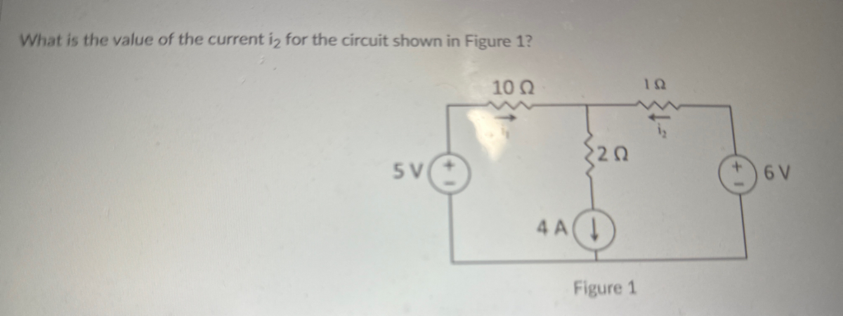
What is the value of the current \( i_2 \) for the circuit shown in Figure 1?
**Circuit Description:**
In Figure 1, a circuit is composed of the following components:
- Two voltage sources of 5V (on the left) and 6V (on the right).
- Three resistors with values:
- 10 Ω (ohms) placed in series with the 5V source.
- 1 Ω placed in series with the 6V source.
- 2 Ω placed in the middle connected in parallel with the two aforementioned resistors.
- A constant current source of 4 A oriented downwards connected at the junction between the 10 Ω and 2 Ω resistors.
**Current Directions:**
- \( i_1 \) is defined as the current flowing through the 10 Ω resistor from left to right.
- \( i_2 \) is defined as the current flowing through the 1 Ω resistor from left to right.
**Analysis Approach:**
In order to find \( i_2 \), we need to apply principles such as Kirchhoff's Laws (KCL and KVL) and Ohm's Law to the described circuit, performing relevant calculations as necessary.
**Circuit Diagram:**
```plaintext
10 Ω 2 Ω 1 Ω
5V ————(Ω)———————(Ω)——————(Ω)———————(+6V)
| | |
| | |
| | |
(A) vol (Ω) vol (-6V)
⬇ (Ω) |
4A | |
| | |
|__________________|_______________|
(Companies in Series and Parallel)
```
**Calculation Steps:**
- Apply KCL at the junctions and KVL around the loops to solve for the unknown currents.
- Use Ohm's Law to find the voltage drops across individual resistors and combine them according to the configuration of the circuit.
**Result:**
Upon following the steps outlined in the analysis approach, the value of the current \( i_2 \) can be accurately determined.
**Conclusion:**
This circuit analysis provides an opportunity to apply fundamental electrical engineering concepts to solve for unknown current

Transcribed Image Text:**Quiz Question on Current Calculation in Electric Circuits**
*Question:*
What is the value of the current \( I_1 \) for the circuit shown in Figure 1?
*Answer Options:*
- ○ Correct Answer Not Given
- ○ \( I_1 = 0.27 \, \text{A} \)
- ○ \( I_1 = 2.0 \, \text{A} \)
- ○ \( I_1 = 3.5 \, \text{A} \)
- ○ \( I_1 = 0.5 \, \text{A} \)
*Explanation:*
This question pertains to the calculation of current in a specific circuit diagram (referred to as Figure 1). The correct answer is one of the given options and represents the computed current \( I_1 \). To solve the problem, students need to analyze the provided circuit diagram (which is not displayed here), apply appropriate electrical laws such as Ohm's Law or Kirchhoff's Laws, and determine the correct current value.
After solving, students can select the answer that matches their calculation. If the exact value does not match any of the given options, they should choose "Correct Answer Not Given".
Remember, understanding circuit diagrams and being able to apply fundamental principles to solve for unknowns like current, voltage, and resistance is crucial for mastering circuit analysis.
**Note:**
Since the figure itself is not provided here, make sure to refer to Figure 1 in your course material to answer this question accurately.
Expert Solution
This question has been solved!
Explore an expertly crafted, step-by-step solution for a thorough understanding of key concepts.

Step by stepSolved in 3 steps with 2 images

Knowledge Booster


Learn more about
Need a deep-dive on the concept behind this application? Look no further. Learn more about this topic, electrical-engineering and related others by exploring similar questions and additional content below.Similar questions
- if an additional resistor with a value of 10M Ohms is placed in parallel with R1,R2, and R3, would you expect to voltage across R1,R2, and R3 to change?arrow_forwardSelect XL1 and XL2, so that maximum power is delivered to the 200 2 load. A 50Ω M I ! B jXLI k=1 ell jXL2 -j1009 200Ωarrow_forwardPlease only typing format solution please Please answer only typing formatarrow_forward
arrow_back_ios
arrow_forward_ios
Recommended textbooks for you
- Introductory Circuit Analysis (13th Edition)Electrical EngineeringISBN:9780133923605Author:Robert L. BoylestadPublisher:PEARSON
 Delmar's Standard Textbook Of ElectricityElectrical EngineeringISBN:9781337900348Author:Stephen L. HermanPublisher:Cengage Learning
 Programmable Logic ControllersElectrical EngineeringISBN:9780073373843Author:Frank D. PetruzellaPublisher:McGraw-Hill Education
  Fundamentals of Electric CircuitsElectrical EngineeringISBN:9780078028229Author:Charles K Alexander, Matthew SadikuPublisher:McGraw-Hill Education
 Electric Circuits. (11th Edition)Electrical EngineeringISBN:9780134746968Author:James W. Nilsson, Susan RiedelPublisher:PEARSON
 Engineering ElectromagneticsElectrical EngineeringISBN:9780078028151Author:Hayt, William H. (william Hart), Jr, BUCK, John A.Publisher:Mcgraw-hill Education,
Introductory Circuit Analysis (13th Edition)
Electrical Engineering
ISBN:9780133923605
Author:Robert L. Boylestad
Publisher:PEARSON
Delmar's Standard Textbook Of Electricity
Electrical Engineering
ISBN:9781337900348
Author:Stephen L. Herman
Publisher:Cengage Learning
Programmable Logic Controllers
Electrical Engineering
ISBN:9780073373843
Author:Frank D. Petruzella
Publisher:McGraw-Hill Education
Fundamentals of Electric Circuits
Electrical Engineering
ISBN:9780078028229
Author:Charles K Alexander, Matthew Sadiku
Publisher:McGraw-Hill Education
Electric Circuits. (11th Edition)
Electrical Engineering
ISBN:9780134746968
Author:James W. Nilsson, Susan Riedel
Publisher:PEARSON
Engineering Electromagnetics
Electrical Engineering
ISBN:9780078028151
Author:Hayt, William H. (william Hart), Jr, BUCK, John A.
Publisher:Mcgraw-hill Education,