
Introductory Circuit Analysis (13th Edition)
13th Edition
ISBN: 9780133923605
Author: Robert L. Boylestad
Publisher: PEARSON
expand_more
expand_more
format_list_bulleted
Related questions
Concept explainers
Question

Transcribed Image Text:### Electrical Engineering Question on Capacitors
In the given circuit diagram, we are asked:
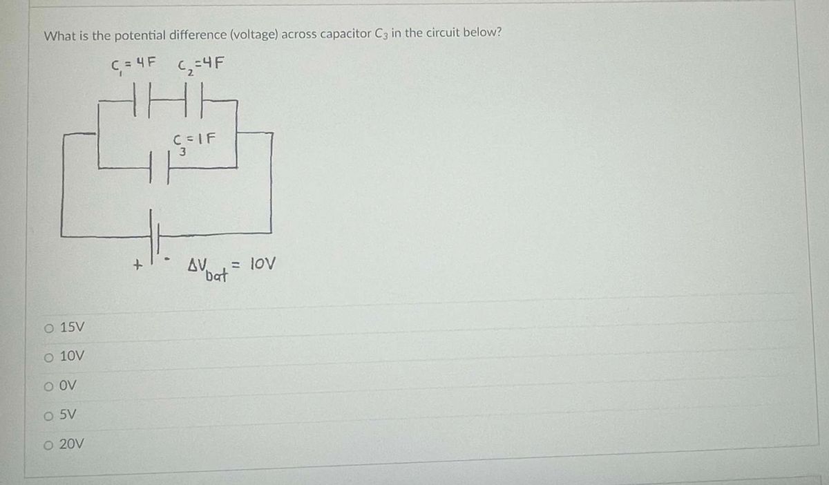
**"What is the potential difference (voltage) across capacitor \(C_3\) in the circuit below?"**
#### Diagram Explanation:
This circuit consists of three capacitors and a battery.
- \(C_1 = 4F\)
- \(C_2 = 4F\)
- \(C_3 = 1F\)
- The battery voltage, \(V_{\text{bat}}\), is 10V
Capacitors \(C_1\) and \(C_2\) are arranged in parallel, and then this combination is in series with capacitor \(C_3\).
#### Potential Answers:
- ⃝ 15V
- ⃝ 10V
- ⃝ 0V
- ⃝ 5V
- ⃝ 20V
By understanding the configuration and calculations involving capacitance in series and parallel, determine the potential difference across capacitor \(C_3\).
---
For further learning, the following concepts can be reviewed:
- Capacitors in Series
- Capacitors in Parallel
- Voltage Division across Capacitors
Expert Solution
This question has been solved!
Explore an expertly crafted, step-by-step solution for a thorough understanding of key concepts.

This is a popular solution

Trending nowThis is a popular solution!

Step by stepSolved in 2 steps

Knowledge Booster


Learn more about
Need a deep-dive on the concept behind this application? Look no further. Learn more about this topic, electrical-engineering and related others by exploring similar questions and additional content below.Similar questions
- 3. (a) (b) An emf, E = 12 V, is wired to a solenoid with self-inductance, L= 0.44 H, two resistors, R₁ = 162, and R₂ = 92, and a two-way switch as shown in the diagram. You first set the switch to position a ... How much energy will be stored in the inductor a long time after you set the switch to position a? L 000 R₁ S R₂ a E You move the switch to position b, starting over at t = 0. Calculate the current through, and voltage across, the inductor immediately after you move the switch from a to b.arrow_forward1) Propose and draw a circuit of a resistive current divider in halfarrow_forwardDescribe in words how the charges behave on capacitors which are in a parallel circuit. How do the individual capacitor charges compare to the charge of the equivalent capacitor?arrow_forward
- energy stored in an inductor hello i would like to get energy stored in an inductor as 1.5E-17 joules around how can i do that regardsarrow_forward.A series RLC circuit contains a 4-kN resistor, an inductor with an inductive reactance (X,) of 3.5 kn, and a capacitor with a capacitive reactance (Xc) of 2.4 kN. A 120-Vac, 60-Hz power source is connected to the circuit. How much voltage is dropped across the inductor?arrow_forward2. What type of energy is stored up in a capacitor? In a storage cell? In an inductive circuit? Why are capacitors not used in place of secondary batteries?arrow_forward
- What is the maximum inductance that can be obtained by connecting four 2-H inductors in series and/or parallel? What is the minimum inductance?arrow_forwardWhen a capacitor is connected to a battery, the plate connected to the terminal ……………………… will be......... 1. +,+ 2.+,- 3.-,+ 4.+.=arrow_forwardAn initially uncharged parallel plate capacitor is connected to a circuit containing a battery with emf -35V and a resistor, R = 3.3M2 as shown in the figure to below. The capacitor whose plates have an area of A= 5.2mm² are separated by a distance of d=3.2mm and one third of the capacitor is filled with a dielectric material, *₁ = 2.5 and the rest (two thirds) is filled with another dielectric material, K₂ = 6.3. At t=0 the switch is closed. 3.6 seconds after the switch is closed the electric field within the first dielectric material (₁) is observed to be 9 x 10³ N/C. Find the potential difference across the capacitor at this instant (t = 3.6s) in terms of permitivity of free space ? Express your answer using zero decimal place. Rarrow_forward
arrow_back_ios
arrow_forward_ios
Recommended textbooks for you
- Introductory Circuit Analysis (13th Edition)Electrical EngineeringISBN:9780133923605Author:Robert L. BoylestadPublisher:PEARSON
 Delmar's Standard Textbook Of ElectricityElectrical EngineeringISBN:9781337900348Author:Stephen L. HermanPublisher:Cengage Learning
 Programmable Logic ControllersElectrical EngineeringISBN:9780073373843Author:Frank D. PetruzellaPublisher:McGraw-Hill Education
  Fundamentals of Electric CircuitsElectrical EngineeringISBN:9780078028229Author:Charles K Alexander, Matthew SadikuPublisher:McGraw-Hill Education
 Electric Circuits. (11th Edition)Electrical EngineeringISBN:9780134746968Author:James W. Nilsson, Susan RiedelPublisher:PEARSON
 Engineering ElectromagneticsElectrical EngineeringISBN:9780078028151Author:Hayt, William H. (william Hart), Jr, BUCK, John A.Publisher:Mcgraw-hill Education,
Introductory Circuit Analysis (13th Edition)
Electrical Engineering
ISBN:9780133923605
Author:Robert L. Boylestad
Publisher:PEARSON
Delmar's Standard Textbook Of Electricity
Electrical Engineering
ISBN:9781337900348
Author:Stephen L. Herman
Publisher:Cengage Learning
Programmable Logic Controllers
Electrical Engineering
ISBN:9780073373843
Author:Frank D. Petruzella
Publisher:McGraw-Hill Education
Fundamentals of Electric Circuits
Electrical Engineering
ISBN:9780078028229
Author:Charles K Alexander, Matthew Sadiku
Publisher:McGraw-Hill Education
Electric Circuits. (11th Edition)
Electrical Engineering
ISBN:9780134746968
Author:James W. Nilsson, Susan Riedel
Publisher:PEARSON
Engineering Electromagnetics
Electrical Engineering
ISBN:9780078028151
Author:Hayt, William H. (william Hart), Jr, BUCK, John A.
Publisher:Mcgraw-hill Education,