What is the angle e based on for a series RC circuit? Oa. Voltage (VR VS. VS) O b. Current (IT vs IR) Oc. Impedance (R vs Z) O d. a and c Oe. b and c Of. none of the above
Q: A lossless transmission line operating at 4.5 GHz has L = 2.4 µH m²¹ and Zo= 85 £2. Calculate the…
A: Please see the attached image for the answer.Explanation:
Q: 7. Use superposition theorem to calculate io in the following circuit. 102 F 24 V 2H m 10 sin(t-30°)…
A: The given circuit isWe need to determine the current, io using superposition theorem.
Q: Parallel connected RC circuit is given. a) Calculate the current Ic through the capacitor b)…
A: In this question, we need to determine the current in capacitor, value of capacitor, total impedance…
Q: Electro Fans has just received an order for one thousand 20-inch fans due week 7. Each fan consists…
A: Product structure all the information related to the product as raw material, components, parts and…
Q: 3. Use Nodal analysis to find (a) current flowing through all the branches in the following…
A: Given:withusing nodal analysis, we need to find:a) current flowing through all branches. b) power…
Q: Assume that the field current of the generator in Problem 1 is adjusted to achieve rated voltage…
A: Given parameters isRated voltage (13.8kV)
Q: 13. The maximum primary moments in unbraced frames almost always occur at the column (A) mid-span…
A: Ans 13 :- option B is correct. Ans 14:- option A is correct. Explanation:Question 13: Option b: This…
Q: A second-order system has a closed loop 25 transfer function given by, 25 G(s) s² + 8s +25 The…
A: The given data is shown below:
Q: 5. Consider an LTI system with the impulse response h(t)=. signal of the system is x(t) = cos(6t+…
A: Given that,Impulse response,;Input signal,
Q: What should be the voltage across the 3H inductor in the below given electrical circuit if the 5V…
A: The given data is shown below:
Q: 2 A lossless transmission line of electrical length = 0.32 is terminated with a complex load…
A:
Q: The circuit below is fed with alternating voltage U with frequency f. a) Calculate the current Ic…
A: We will solve for each parallel brancha.) has in branch2 the value from C is unknown so we save it…
Q: have a question on why did you use 3 in the equation when solving for the ripple voltage
A: Forward bias of a diode: When Anode voltage of a diode greater than the cathode voltage of a diode…
Q: In the circuit in figure 4 (R = 1, C = 1.5 μF, 2.3 V), = the switch is initially open. How long does…
A: In this question, we need to determine the time taken to charge the capacitor to 60% after switch is…
Q: R1=220 2 R2=68 Ω EV + R₁ R2 A B
A: The given circuitHere given that circuit is supplied sinusoidal voltage so supplied voltage assume…
Q: You and your crew have made it through the night and the day has brought more warmth. After…
A: According to the question, we need to modify the circuit given below so that the output voltage is…
Q: E7.21 A unity feedback system has a loop transfer function Ks = L(s) Ge(s)G(s) = s3 +882 +12' Sketch…
A: Given:Loop transfer function, we need to sketch: the root locus and determine the gain K when the…
Q: 1- Refer to the transformer of the figure. a) Place polarity dots on windings 3 and 4. b) State…
A: a) Place polarity dots on winding 3 and 4b) State number of turns of winding 4
Q: Two point charges are located at a distance a from the z = 0 plane along the z-axis. Calculate the…
A: see belowExplanation:and Thanks Any problem please ask
Q: Construct the circuit in Figure 1 in the Circuit JS simulator. Note that the voltage source is given…
A: Please refer below pages.Explanation:Step 1: Step 2: Step 3:
Q: 2. Obtain the equivalent resistance at the terminals a-b for the given circuit.
A: The given data is shown below:
Q: I need the solution to the question.
A: Answers are as follows:(1) -8.33 Volt(2) 6.939 Watt(3) 20 kilo-ohm(4) Theoretically infinite amount…
Q: One line voltage of a balanced Y-connected source is VAB = 180-20° V. If the source is connected to…
A:
Q: Consider the circuit shown in the given figure. (Given: A = 4.000.) 10 Ω ww 1 H 2 cos 101 V 5H 3H ΑΩ…
A: Average power, also known as real power or active power, is the power consumed by a circuit that is…
Q: The circuit in the figure is supplied with a sinusoidal alternating voltage. a) Calculate the source…
A: Here we have calculated all the parameters that have been asked. If any doubt please feel free to…
Q: A new model of electric vehicle contains two essential electronic components. Ifeither one of the…
A: The car is predicted to become unusable after approximately 11.11 years.Explanation:Step 1:…
Q: A salient - pole 3 phase cylindrical synchronous machine has a direct-axis reactance equal to two…
A: This is a synchronous machine
Q: 2. Calculate the effective densities of states for electrons and holes at room temperature for…
A: Refer explanationExplanation:
Q: An RLC circuit with input voltage E(t) is described. Find the current I(t) using the given initial…
A: An RLC series circuit is a circuit that contains a resistor (R), an inductor (L), and a capacitor…
Q: (Ex H (5) = 52-55+6 find Zeros as poles then five system is stable not stable 2
A:
Q: For a certain alternating current, i(t), [A] i = 2 ⋅ sin (500 π ⋅ t + ) π, where the time is in…
A: The objective of the question is to determine the peak value, rms value, period, and frequency of…
Q: Please show all work!!
A: ic(t)=−6.4te−400tmAwaveform is shown belowExplanation:
Q: to the Passive RLC Filter Shown R= 1500, L=22mH and c= 0.56nt, Determine the Following WO (6) Q A…
A:
Q: In the simulation, which of the following statements correctly compare the ideal parallel plate…
A: The objective of the question is to compare the ideal parallel plate capacitor to the ideal…
Q: please help answer question with full workings thank you!! answers: a) Vo(s) = 325000/ s(s+ 1000)…
A: Shown in detailed below. In case of Doubts please do let me know Explanation:Step 1:Step 2:Step…
Q: An analog signal xa(t) has a continuous fourier transform that follows the attached image. If the…
A:
Q: Using an LBA camera, profile, describe and comment on the intensity distribution of the beam exiting…
A: The objective of the question is to understand the intensity distribution of the laser beam exiting…
Q: Determine the value of y[n] by using z-transforms to solve for Y(z) and then converting back to…
A: The value of Y[n]:- y[n]=(5/13)(0.4)n u[n] + 1/13 (3)n u[n] full answer i=with…
Q: 1- The no-load current drawn by transformer is usually, the per cent of the full-load current is a)…
A: The no-load current drawn by transformer is usually the percent of the full-load current is ---a.…
Q: 5.2-8 A signal bandlimited to 1 MHz is sampled at a rate 30% above the Nyquist rate and quantized…
A: A signal bandlimited to 1 MHz is sampled at a rate 30% above the Nyquist rate and quantized into…
Q: 22. The flip-flop in Figure 7-79 is initially RESET. Show the relation between the Q output and the…
A: Given:The flip-flop is initially reset and the propagation delay is .we need to show:the relation…
Q: Consider the amplifier in the figure given below, where VA = 50 V, VCC = 20 V, VEE = 20 V, IEE = 350…
A: A difference amplifier, also known as a differential amplifier or difference op-amp, is an…
Q: BJT Circuit Theory: I have this following circuit but its not producing the correct output. My input…
A: Please refer below pages.If you have any doubts please feel free to ask.Explanation:Step 1: Step 2:…
Q: Please solve all showing all the steps in detail
A: (a) A = 0.9676+j0.00324B = 7.2+j72 ohmC = (-1.458+j885.82)*10-6 mhoD = 0.9676+j0.00324 (b) % Eff =…
Q: R1 R2 R3 A R4 R5 (V) U=27 V, R1=1 Ω R2=1 Q R3=4.7 Q R4=7.3 Q R5=4.8 Ω
A: “Since you have posted a question with multiple sub parts, we will provide the solution only to the…
Q: 3. For the following circuit, L₁ = 15 mH, L₁ = 20 mH, and M = 5 mH. Determine the 7-equivalent…
A: The given mutually coupled circuit needs to be converted into equivalent circuit.
Q: V10 o +3 V 6.2 ΚΩ 180 ΚΩ 0 V11 0 V12 300 ΚΩ 10 ΚΩ -3 V (e) Figure P6.61(e) *6.62 Repeat the analysis…
A: Given circuit: -Find: -The labeled node voltages and branch currents.Solution: -Let's solve the bias…
Q: Design a " 2 to 4" Decoder with SEL' (active lo) 1. Generate the logic gates and the equations 2.…
A:
Q: P1. For the circuit in Fig. 1 find the values of i, v₁, 11, 12, Vo, IL, io, and vo/v1. 1 ΚΩ w V₁ =…
A:
Q: What is the FOA ratings in MVA
A:
Please answer in typing format
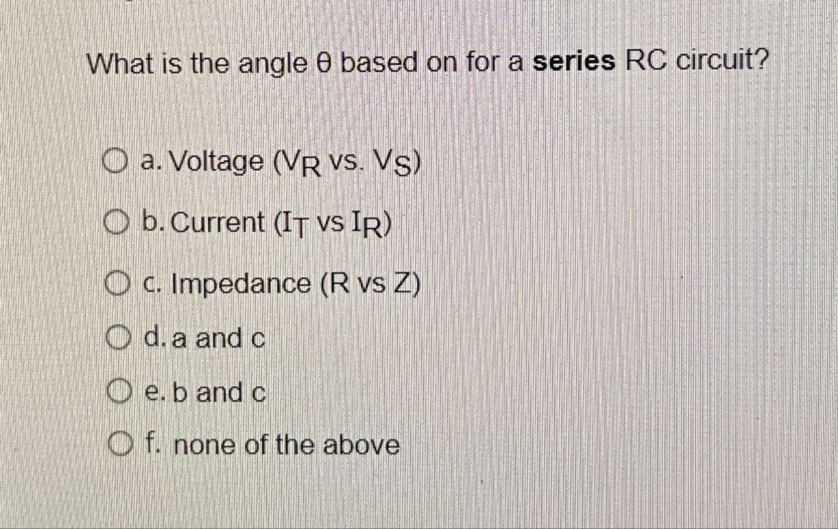
Step by step
Solved in 3 steps
- for the R-th part. isn't R3 and R5 in series not parrallel? If not, explain why. If so, fix the solution. THank you.For the circuit diagram in figure Q22: which of the following is the total impedance? 12 Ri 10R R2||5R Figure Q22 V 220V40 50HZ L1 315mH C1=350uF O a. 3.33/0° O b. 4.71290°2 O c. 7.3304-19.66° O d. 10.37261.19°24) Label magnitude and direction for the currents through R1, R2, R3, R4 & R5. Show all work.
- An A.C Bridge as shown in the figure is used to measure unknown inductance L1. in companion with capacitance What would be the quality factor if the frequency is 1500 Hz & the various parameter are as below- 120VShow final CircuitDC-AC Circuits Express R1 using Rx, Ry, and Rz when performing wye to delta conversion R3 Rx Rz R2 R1 Ry O A. (Rx+Ry)(Ry+Rz)(Rx+Rz) Rx В. RyRz Rx+Ry+Rz O C. Ry+Rz RXRYRZ O D. RXRYRZ Ry+Rz OE. RxRy+RyRz+RXRZ Rx
- PleaseQ2. For the circuit shown in figure (a), let the frequency is 1KHZ, and V1 = 20Vms, draw the following: 100uF C2 V1 1000UF R1 VSINE 2K A. Impedance diagram B. Voltages phasor diagram. C. Measure the voltage across R1, Vin, and the capacitors, C1, C2 us ng the oscillscope using PROTEUS software. D. Measure the current in the circuit using DMM E. From the above measurments verify your result.Answer the following with illustration and solution. 1.) A circuit consisting of a resistor of 5kohms in series with a capacitor of 10 nanofarad is connected across a 16v sinusoidal supply. Calculate the output voltage at a frequency of 60Hz and again at frequency of 120Hz. This is the example/guide that might help.
- The dioces are ideal. write the Fransfer Characteidie equati ons ( &, as a funchiar g &) Plot &o agaiwet &, imdicaling all intrcepts, slopes and Volt ope lerels. Sketch bo f bq =40 sin wt. Indicate al voltage lezels - %3D 1OK lok lovDraw a seven-segment display, show the number highlighted in figure 1 (d3 -d0 are the input, a -g are the outputs). III. Simulation Wavetorm Editor - Cers/Ahmad Fainuz/Desanop/DLD Lab Practice/bedseg - beaeg - bcaseg 2018o03121936sim.vwwt Ee ep Ea w smutation search altera.com Haster Time Bar: ops Pointer: s29 us Start End iterval 529 us o ps 0 ps २ 2.56 us S12 us 75 us 10.24 us 12 s 15.36 us 172 us value at Name Ops do Figure 1for The Circuit shown in figure if CB = 50) find The values of CIe). and of Then express The c hamge in value by apercentage + 15レ こ RB2 = so KQ RE 3K52