
Introductory Circuit Analysis (13th Edition)
13th Edition
ISBN: 9780133923605
Author: Robert L. Boylestad
Publisher: PEARSON
expand_more
expand_more
format_list_bulleted
Related questions
Question
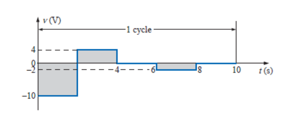
what is rms value of below signallll.

Expert Solution
This question has been solved!
Explore an expertly crafted, step-by-step solution for a thorough understanding of key concepts.

This is a popular solution

Trending nowThis is a popular solution!

Step by stepSolved in 3 steps with 3 images

Knowledge Booster


Learn more about
Need a deep-dive on the concept behind this application? Look no further. Learn more about this topic, electrical-engineering and related others by exploring similar questions and additional content below.Similar questions
- The average value of the output voltage with PWM is Vo = 5 V. If the on state duration Ton is 5 µs and supply voltage Vin = 20 V, find the duty ratio d, switching period Ts and switching frequency fs of the system. Draw the waveforms for Vin and Vo voltages stating on and off durations.arrow_forwardPeriodic analog signals can be classified as simple or composite, how, give an example of both. The sine wave is the most fundamental form of a periodic analog signal. How can it be represented as a sine wave with help of parameters and diagrams?arrow_forwardQ2) Design a Bridge FWR to supply a load of (1002) with the waveform shown in figure from the main power supply of (220 Vrms). Find: - 1- The transformer turns ratio (a). 2- The ripple voltage. Vot Vm = 12 V 3- The Vde value. 4- The RMS value of the output voltage. 5- The ripple factor. 6- The value of capacitor filter. Vip = 0.1 V (assume ideal diodes) T=0.01 sec. tisec) Q3) V in Design a regulated circuit to supply a constant voltage of (10 V) across a resistive load of (50 2). The input voltage is shown in the figure. The minimum current for the Zener diode operation is (Izk=5mA). Find the 15 V 15 maximum power dissipated in the Zener diode. 12.5 12 V 10arrow_forward
- What is the DC gain of the given circuit above?arrow_forwardWhat is coupled magnitudes? What is the significance of this difference in the coupled magnitudes to the lay-out of circuit fast signals?arrow_forward7-22 Abasehand signal with frequency components from near de to 15 kHz frequency modulates a 200-kHz carrier, and the frequency deviation is +3 kHz. The signal is applied as the input to a cascade of two frequency triplers and one frequency doubler. Determine the output (a) center fre- quency, (b) frequency deviation, and (c) deviation ratio.arrow_forward
- Consider a step down converter supplied by a DC power source of magnitude Vs = 220 V. The switching period is 0.1 ms and the duty cycle k is set to 0.5. The load is an inductive load with R=5 Ohms and L=10 mH. The switch is ideal. The RMS converter current IR is equal to 15.56A. The ripple factor of the input current RFs would be equal to: Select one: a. 0% Ob. 50% Oc. 100% d. None of thesearrow_forward4.5 In a class-A chopper circuit an ideal battery of terminal voltage 220 V supplies a load of resistance10 2. The chopping frequency is f=1 kHz and the duty cycle is set to be 0.5. Determine: (a) The average output voltage. (b) The rms output voltage. (c) The chopper efficiency. (d) The ripple factor. (e) The fundamental component of output harmonic voltage.arrow_forward
arrow_back_ios
arrow_forward_ios
Recommended textbooks for you
- Introductory Circuit Analysis (13th Edition)Electrical EngineeringISBN:9780133923605Author:Robert L. BoylestadPublisher:PEARSON
 Delmar's Standard Textbook Of ElectricityElectrical EngineeringISBN:9781337900348Author:Stephen L. HermanPublisher:Cengage Learning
 Programmable Logic ControllersElectrical EngineeringISBN:9780073373843Author:Frank D. PetruzellaPublisher:McGraw-Hill Education
  Fundamentals of Electric CircuitsElectrical EngineeringISBN:9780078028229Author:Charles K Alexander, Matthew SadikuPublisher:McGraw-Hill Education
 Electric Circuits. (11th Edition)Electrical EngineeringISBN:9780134746968Author:James W. Nilsson, Susan RiedelPublisher:PEARSON
 Engineering ElectromagneticsElectrical EngineeringISBN:9780078028151Author:Hayt, William H. (william Hart), Jr, BUCK, John A.Publisher:Mcgraw-hill Education,
Introductory Circuit Analysis (13th Edition)
Electrical Engineering
ISBN:9780133923605
Author:Robert L. Boylestad
Publisher:PEARSON
Delmar's Standard Textbook Of Electricity
Electrical Engineering
ISBN:9781337900348
Author:Stephen L. Herman
Publisher:Cengage Learning
Programmable Logic Controllers
Electrical Engineering
ISBN:9780073373843
Author:Frank D. Petruzella
Publisher:McGraw-Hill Education
Fundamentals of Electric Circuits
Electrical Engineering
ISBN:9780078028229
Author:Charles K Alexander, Matthew Sadiku
Publisher:McGraw-Hill Education
Electric Circuits. (11th Edition)
Electrical Engineering
ISBN:9780134746968
Author:James W. Nilsson, Susan Riedel
Publisher:PEARSON
Engineering Electromagnetics
Electrical Engineering
ISBN:9780078028151
Author:Hayt, William H. (william Hart), Jr, BUCK, John A.
Publisher:Mcgraw-hill Education,