
Related questions
Concept explainers


The beam will only give the vertical reaction. There will not be any horizontal reaction from the beam. Let's draw the moment diagram parts. The reaction at support B gives a triangular moment and the moment M remains the constant.
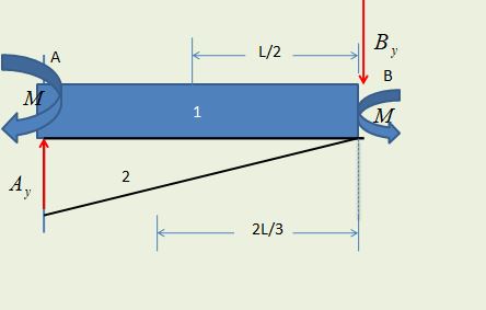
Section (1) in the diagram shows the region or area due to the moment in a rectangular form while the triangular area (2) is due to the reaction of support B.
Now apply the moment area method. Consider the moment about point B. The distance of the centroid is given by L/2 and 2L/3.
The area due to the moment M (rectangle), A1 = ML
The area due to the support reaction (trinagle), A2 = -1/2 L(ByL)
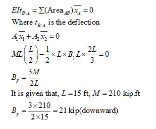
Now apply moment area method,
The boundary condition is that deflection remains zero at end A and end B.

Trending nowThis is a popular solution!

Step by stepSolved in 3 steps with 2 images


- d of the test. Tó gỗ back COMPLETED: 0 % Question: 1 of 21 QUESTION: According to OSHA's key forklift loading requirements, when should the forks be tilted forward? The forks can be tilted forward: POSSIBLE ANSWERS: If carrying a load that is off-center. Olf the forklift is unattended or powered off. When picking up or dropping off a load. Whenever the forklift is in use. Submit Answer Skip Question Back to Home | Sup 6 étv MacBook Air 80 DII DD F2 F3 F4 F5 F6 F7 F8 F9 @ 23 $ & * 2 3 4 6. 7 8. W E R T Y U S D F G H J K L C V M Barrow_forwardItem 1 used to intermittently operate a piece of equipment at the end of a lifter arm. The lifter is in contact with the highest point of the cam at the instant shown and the lifter is constrained to move only in the vertical direction. The cam has a radius of r = 4.5 in and is rotating about point O, which is offset from the center by a distance c = 3.0 in. The cam's angular position is measured from the positive x axis and is positive clockwise. The angular velocity and acceleration are positive clockwise. (Figure 1) Figure (0,0 36°F Clear r W 1 of 1 Par Find align Expr Vie Omin Subn Provide Feedbarrow_forwardThis is Mechanical Engineering Pneumatics. Draw the schematic diagram of the block diagram shown - pneumatic door open close system. Example of schematic diagram is shown below.arrow_forward
- Elements Of ElectromagneticsMechanical EngineeringISBN:9780190698614Author:Sadiku, Matthew N. O.Publisher:Oxford University Press
 Mechanics of Materials (10th Edition)Mechanical EngineeringISBN:9780134319650Author:Russell C. HibbelerPublisher:PEARSON
 Thermodynamics: An Engineering ApproachMechanical EngineeringISBN:9781259822674Author:Yunus A. Cengel Dr., Michael A. BolesPublisher:McGraw-Hill Education
  Control Systems EngineeringMechanical EngineeringISBN:9781118170519Author:Norman S. NisePublisher:WILEY
 Mechanics of Materials (MindTap Course List)Mechanical EngineeringISBN:9781337093347Author:Barry J. Goodno, James M. GerePublisher:Cengage Learning
 Engineering Mechanics: StaticsMechanical EngineeringISBN:9781118807330Author:James L. Meriam, L. G. Kraige, J. N. BoltonPublisher:WILEY