
Introductory Circuit Analysis (13th Edition)
13th Edition
ISBN: 9780133923605
Author: Robert L. Boylestad
Publisher: PEARSON
expand_more
expand_more
format_list_bulleted
Related questions
Concept explainers
Question
Solve the Assesment problem

Transcribed Image Text:Zc = i
= -i
(5000)(5)
j40 2.
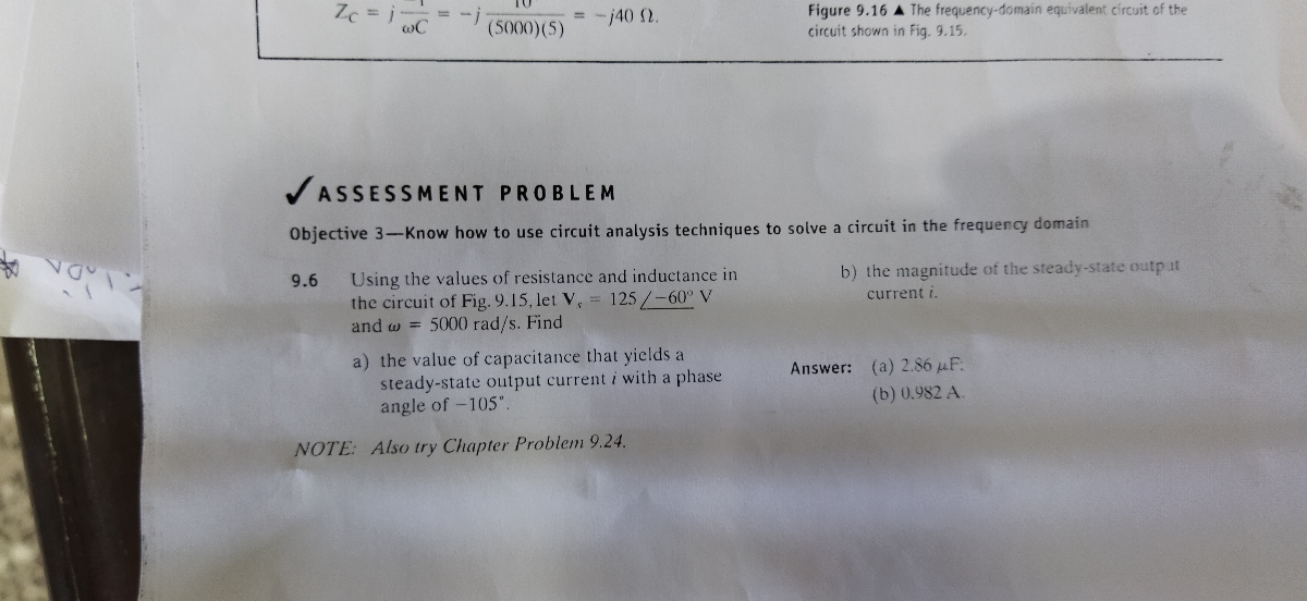
Figure 9.16 A The frequency-domain equivalent circuit of the
circuit shown in Fig. 9.15.
VASSESSMENT PROBLEM
Objective 3-Know how to use circuit analysis techniques to solve a circuit in the frequency domain
b) the magnitude of the steady-state outp ut
Using the values of resistance and inductance in
the circuit of Fig. 9.15, let V, = 125/-60° V
and w = 5000 rad/s. Find
9.6
current i.
a) the value of capacitance that yields a
steady-state output current i with a phase
angle of -105".
Answer: (a) 2.86 uF:
(b) 0.982 A.
NOTE: Also try Chapter Problem 9.24.

Transcribed Image Text:V.b Series, Parallel, and Delta-to-Wye Simplirk atiors
323
Example 9.6
Combining Impedances in Series
A 90 1 resistor, a 32 mH inductor, and a SaF
capacitor are connected in series across the termi-
The phasor transforin of , is
Fig. 9.15. The steady-state expTession for the seurce
I ANOS se asnos adeyor epiosnuns e jo speu
Figure 9.16 illustrates the frequency-domain
cquivalent circut of the circuit shown in Fig 915.
b) We cumpute the plusor current simply by divid-
ing the voltage of the voltage source by the equiv-
alent impedance between the terminals a,b. From
Eq 9.45,
A GOE + 0OUS) sea psL S 'a aieyon
circuit.
uapAnbo ureurop-kouanbaij ay 1anasuo) (e
b) Calculate the steady-state current i by the plhasor
method.
0-f - U1 + cx = "7
Thus
- $/-23, 13 A.
Figure 9.15 A The circui: for Exam ple 9.5.
150 /53.13
We may now write the steady-state expression
for directly:
Solution
=Scos (50 - 23.13) A.
w = S0XX0 rad/s. Therefore the impedance of the
32 mH inductor is
and the impedance of the capacitor is
Figure 9.16 A TIhe frequenzy demain equivalent circuit ef the
CIcui: shewn in fig 9.15.
" = z
VASSESSMENT PROBLEM
Objective 3-Know how to use circuit analysis techniques to solve a circuit in the frequency domain
Using the values of resistance and inductance in
the circuit of Fig. 9.15, let V, 125/-60" V
and ow 5000 rad/s. Find
9.6
b) the magnitude of the steady-state outpat
carrent i.
a) the value of capacitance that yields a
steady-state oulpat curreat i with a phase
angle of -105.
98z (e) uaMsuy
V Z560 (4)
NOTE Also try Chopter Problem 9.24.
Expert Solution
This question has been solved!
Explore an expertly crafted, step-by-step solution for a thorough understanding of key concepts.

This is a popular solution

Trending nowThis is a popular solution!

Step by stepSolved in 2 steps

Knowledge Booster


Learn more about
Need a deep-dive on the concept behind this application? Look no further. Learn more about this topic, electrical-engineering and related others by exploring similar questions and additional content below.Similar questions
- Find out the VT, RT, 12, I5, 17, 18, 19, V4, and V9 for the given circuit: R1 R2 7.20 60 R4 100 11 R3 25A 3640 R5 120 R8 R7 100 640 R9 R6 60 60 b)arrow_forwardQuestion Completion Status: a C2 C3 C1 Find Ceg at the (a,b) terminals given that C1-9.7 HF C2-2.8 uF C3-8.8 uF Ca-7.9 uF Note: Your answer should be round to the nearest single digit decimal place. Your answer will be in micorFarads. For example, if you compute 1.63x10-0, then enter 1.6 as your answer. 49 F P Type here to search Cop home iprt sc delete 144arrow_forwardThe subtraction of your matrix is wrong. You should have (s-1), not just s. Could you please verify your answer? My final answer is -1/10.arrow_forward
Recommended textbooks for you
- Introductory Circuit Analysis (13th Edition)Electrical EngineeringISBN:9780133923605Author:Robert L. BoylestadPublisher:PEARSON
 Delmar's Standard Textbook Of ElectricityElectrical EngineeringISBN:9781337900348Author:Stephen L. HermanPublisher:Cengage Learning
 Programmable Logic ControllersElectrical EngineeringISBN:9780073373843Author:Frank D. PetruzellaPublisher:McGraw-Hill Education
  Fundamentals of Electric CircuitsElectrical EngineeringISBN:9780078028229Author:Charles K Alexander, Matthew SadikuPublisher:McGraw-Hill Education
 Electric Circuits. (11th Edition)Electrical EngineeringISBN:9780134746968Author:James W. Nilsson, Susan RiedelPublisher:PEARSON
 Engineering ElectromagneticsElectrical EngineeringISBN:9780078028151Author:Hayt, William H. (william Hart), Jr, BUCK, John A.Publisher:Mcgraw-hill Education,
Introductory Circuit Analysis (13th Edition)
Electrical Engineering
ISBN:9780133923605
Author:Robert L. Boylestad
Publisher:PEARSON
Delmar's Standard Textbook Of Electricity
Electrical Engineering
ISBN:9781337900348
Author:Stephen L. Herman
Publisher:Cengage Learning
Programmable Logic Controllers
Electrical Engineering
ISBN:9780073373843
Author:Frank D. Petruzella
Publisher:McGraw-Hill Education
Fundamentals of Electric Circuits
Electrical Engineering
ISBN:9780078028229
Author:Charles K Alexander, Matthew Sadiku
Publisher:McGraw-Hill Education
Electric Circuits. (11th Edition)
Electrical Engineering
ISBN:9780134746968
Author:James W. Nilsson, Susan Riedel
Publisher:PEARSON
Engineering Electromagnetics
Electrical Engineering
ISBN:9780078028151
Author:Hayt, William H. (william Hart), Jr, BUCK, John A.
Publisher:Mcgraw-hill Education,