Introductory Circuit Analysis (13th Edition)
13th Edition
ISBN: 9780133923605
Author: Robert L. Boylestad
Publisher: PEARSON
expand_more
expand_more
format_list_bulleted
Concept explainers
Question
do fast i will 10 upvotes

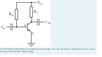
Transcribed Image Text:RB
RC
Vcc
V
in
H
B
E
out
A BJT (ẞ=200) is implemented in an amplifier circuit, with a Vcc of 15 volts. One wishes to set the Q point at Ic = 4.2 mA
and VCE = 6.54 volts (DC). Determine RB-
Expert Solution
This question has been solved!
Explore an expertly crafted, step-by-step solution for a thorough understanding of key concepts.
Step by stepSolved in 3 steps with 1 images

Knowledge Booster
Learn more about
Need a deep-dive on the concept behind this application? Look no further. Learn more about this topic, electrical-engineering and related others by exploring similar questions and additional content below.Similar questions
- 3. Draw the DC load line for the circuit diagram sown in Figure. What will be the Q point if the zero signal base current is 25µA and β = 50.arrow_forwardIs=20*10-16 B=100 question A&Barrow_forwardTransform and draw the equivalent small signal circuit model using ONLY theHYBRID-PI model.arrow_forward
- Draw the small signal model of the circuit and derive the equations for vIN and vOUTarrow_forward3. Given Vec=100V, R,=2002, B=100, VBB-5V, flip the switch to close, and Ic=0.4A, 1) Determine Ip. 2) Determine Rg- 3) Determine VCE Ve RL 18 Vc VE VBBarrow_forwardFrom the circuit below, determine the output peak voltage Vm ? Np:Ns 6:1 Vp 120 Vac out 60 Hz DA R = 200 2 O Ovpeak O 169.71Vpeak O 28.28Vpeak O 1018.23Vpeakarrow_forward
- Consider the circuit of Figure 1, with a periodic square signal voltage source at a frequency f = 500 [Hz], consider R = 1600 [22]. Solve the circuit and plot on graph paper (minimum 10 values between 0 and 2 milliseconds) the total current response, taking into account the source Vin = 24 [Vp]. Note: identify in the graph maximum and minimum points of the total current response. Vin CH1 L m 160 mH, 4 Q CH2 REF Figure 1. Series RL circuit. Note: to do by differential equations and not to use laplacearrow_forwardif you design differentiator to differentiate input signal varies in frequency between 1 KHz and 20 KHz then find , If capacitor =0.1 micro farad and feedback resistance=1.6 k ohm then Corner frequency =..... KHz O10 O20 030 040arrow_forward60 fi fs f2 Qs = f = 12,000 Hz the cutoff frequency f2 =.............Hz ▬▬ Q Search book.pat digital-fundamental...arrow_forward
- A type II compensator implementation for the above Buck converter is shown below. Ce2 Vout Cet HH Ret Vctrl R2 E/A Vset What should be the voltage Vref in the above type II compensator to produce 5V DC output if R# = 4k and R2=1k. а. Vet b. Write the small signal gain equation (-ctrl) between Vetrl and Vout- out с. Does R2 present in the above gain equation. Please add some explanation. d. How many poles and how many zeros are produced by this type II compensator?arrow_forward6. An AC precision integrator is desired for a particular application to perform the operation: Vo'(t) = -1200 Vi(t) dt The primes indicate the ac portions of the respective functions. The lowest frequency other than a possible de component of the input signal is estimated to be 1.5 kHz. Determine a suitable design. 7. A low frequency differentiator is desired for a particular application n to perform the operation Vo(t) = -0.002 dvi(t)/ dt Based on a periodic signal with a frequency of 1 kHz, determine a suitable design. 8. Design an astable 555 timer circuit to produce 1kHz square wave, where TH = 0.35 ms and T₁ = 0.65 ms. Select C = 0.01 UE, Determine R₁ and Ra. 9. Design a monostable 555 timer circuit to produce an output pulse 5 ms wide. 10. Using op amps with Xsat = +/- 13 V, design a square/ triangular wave function generator circuit to generate 2 kHz triangular wave with a peak-to-peak voltage of 12 V. 11. Design a non inverting Schmitt trigger circuit with VT to be adjustable…arrow_forwardclear and correct or dislikearrow_forward
arrow_back_ios
arrow_forward_ios
Recommended textbooks for you
 Introductory Circuit Analysis (13th Edition)Electrical EngineeringISBN:9780133923605Author:Robert L. BoylestadPublisher:PEARSON
 Delmar's Standard Textbook Of ElectricityElectrical EngineeringISBN:9781337900348Author:Stephen L. HermanPublisher:Cengage Learning
 Programmable Logic ControllersElectrical EngineeringISBN:9780073373843Author:Frank D. PetruzellaPublisher:McGraw-Hill Education
 Fundamentals of Electric CircuitsElectrical EngineeringISBN:9780078028229Author:Charles K Alexander, Matthew SadikuPublisher:McGraw-Hill Education
 Electric Circuits. (11th Edition)Electrical EngineeringISBN:9780134746968Author:James W. Nilsson, Susan RiedelPublisher:PEARSON
 Engineering ElectromagneticsElectrical EngineeringISBN:9780078028151Author:Hayt, William H. (william Hart), Jr, BUCK, John A.Publisher:Mcgraw-hill Education,

Introductory Circuit Analysis (13th Edition)
Electrical Engineering
ISBN:9780133923605
Author:Robert L. Boylestad
Publisher:PEARSON

Delmar's Standard Textbook Of Electricity
Electrical Engineering
ISBN:9781337900348
Author:Stephen L. Herman
Publisher:Cengage Learning

Programmable Logic Controllers
Electrical Engineering
ISBN:9780073373843
Author:Frank D. Petruzella
Publisher:McGraw-Hill Education

Fundamentals of Electric Circuits
Electrical Engineering
ISBN:9780078028229
Author:Charles K Alexander, Matthew Sadiku
Publisher:McGraw-Hill Education

Electric Circuits. (11th Edition)
Electrical Engineering
ISBN:9780134746968
Author:James W. Nilsson, Susan Riedel
Publisher:PEARSON

Engineering Electromagnetics
Electrical Engineering
ISBN:9780078028151
Author:Hayt, William H. (william Hart), Jr, BUCK, John A.
Publisher:Mcgraw-hill Education,