Introductory Circuit Analysis (13th Edition)
13th Edition
ISBN: 9780133923605
Author: Robert L. Boylestad
Publisher: PEARSON
expand_more
expand_more
format_list_bulleted
Concept explainers
Question

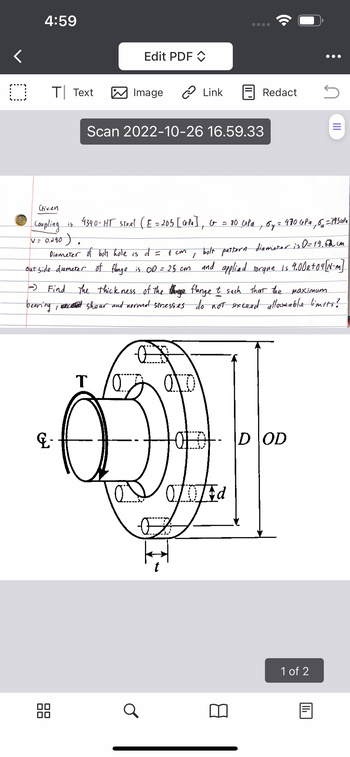
Transcribed Image Text:**Mechanical Engineering Flange Design**
**Given Data:**
- Coupling is made of 4340-HT steel.
- Elastic Modulus (\(E\)) = 205 GPa
- Shear Modulus (\(G\)) = 80 GPa
- Yield Strength (\(\sigma_y\)) = 470 MPa
- Ultimate Strength (\(\sigma_u\)) = 745 MPa
- Poisson's Ratio (\(\nu\)) = 0.28
**Specifications:**
- Diameter of bolt hole (\(d\)) = 1 cm
- Bolt pattern diameter (\(D\)) = 19.62 cm
- Outside diameter of flange (\(OD\)) = 25 cm
- Applied torque (\(T\)) = \(4.00 \times 10^4\) N-m
**Objective:**
Determine the thickness (\(t\)) of the flange such that the maximum bearing, shear, and normal stresses do not exceed allowable limits.
**Diagram Explanation:**
The diagram shows a mechanical coupling featuring a flange with a bolt pattern. The flange has circular holes for bolts and a central axis indicated by \(G\). Key dimensions are:
- \(t\): thickness of the flange
- \(d\): diameter of the bolt holes
- \(D\): bolt pattern diameter
- \(OD\): outside diameter of the flange
The torque (\(T\)) is applied at the central hub of the flange. The image illustrates the relationship between these key dimensions, which are critical for calculating stress distribution in mechanical connections.
Expert Solution
This question has been solved!
Explore an expertly crafted, step-by-step solution for a thorough understanding of key concepts.
This is a popular solution
Trending nowThis is a popular solution!
Step by stepSolved in 2 steps

Knowledge Booster
Learn more about
Need a deep-dive on the concept behind this application? Look no further. Learn more about this topic, electrical-engineering and related others by exploring similar questions and additional content below.Similar questions
- "Electrical machines/ I need a complete and clear solution for all 7 sub-questions of a single question. Thank you."arrow_forwardRefer attached figure of an axial reluctance force actuator on Image 1. While ignoring core reluctances, find the reluctance force, F, if x = 0.004 m and I = 5 A using the atached force expression on attached image 2.arrow_forwardPlease answer in typing format solutionarrow_forward
arrow_back_ios
arrow_forward_ios
Recommended textbooks for you
 Introductory Circuit Analysis (13th Edition)Electrical EngineeringISBN:9780133923605Author:Robert L. BoylestadPublisher:PEARSON
 Delmar's Standard Textbook Of ElectricityElectrical EngineeringISBN:9781337900348Author:Stephen L. HermanPublisher:Cengage Learning
 Programmable Logic ControllersElectrical EngineeringISBN:9780073373843Author:Frank D. PetruzellaPublisher:McGraw-Hill Education
 Fundamentals of Electric CircuitsElectrical EngineeringISBN:9780078028229Author:Charles K Alexander, Matthew SadikuPublisher:McGraw-Hill Education
 Electric Circuits. (11th Edition)Electrical EngineeringISBN:9780134746968Author:James W. Nilsson, Susan RiedelPublisher:PEARSON
 Engineering ElectromagneticsElectrical EngineeringISBN:9780078028151Author:Hayt, William H. (william Hart), Jr, BUCK, John A.Publisher:Mcgraw-hill Education,

Introductory Circuit Analysis (13th Edition)
Electrical Engineering
ISBN:9780133923605
Author:Robert L. Boylestad
Publisher:PEARSON

Delmar's Standard Textbook Of Electricity
Electrical Engineering
ISBN:9781337900348
Author:Stephen L. Herman
Publisher:Cengage Learning

Programmable Logic Controllers
Electrical Engineering
ISBN:9780073373843
Author:Frank D. Petruzella
Publisher:McGraw-Hill Education

Fundamentals of Electric Circuits
Electrical Engineering
ISBN:9780078028229
Author:Charles K Alexander, Matthew Sadiku
Publisher:McGraw-Hill Education

Electric Circuits. (11th Edition)
Electrical Engineering
ISBN:9780134746968
Author:James W. Nilsson, Susan Riedel
Publisher:PEARSON

Engineering Electromagnetics
Electrical Engineering
ISBN:9780078028151
Author:Hayt, William H. (william Hart), Jr, BUCK, John A.
Publisher:Mcgraw-hill Education,