
Introductory Circuit Analysis (13th Edition)
13th Edition
ISBN: 9780133923605
Author: Robert L. Boylestad
Publisher: PEARSON
expand_more
expand_more
format_list_bulleted
Related questions
Concept explainers
Question
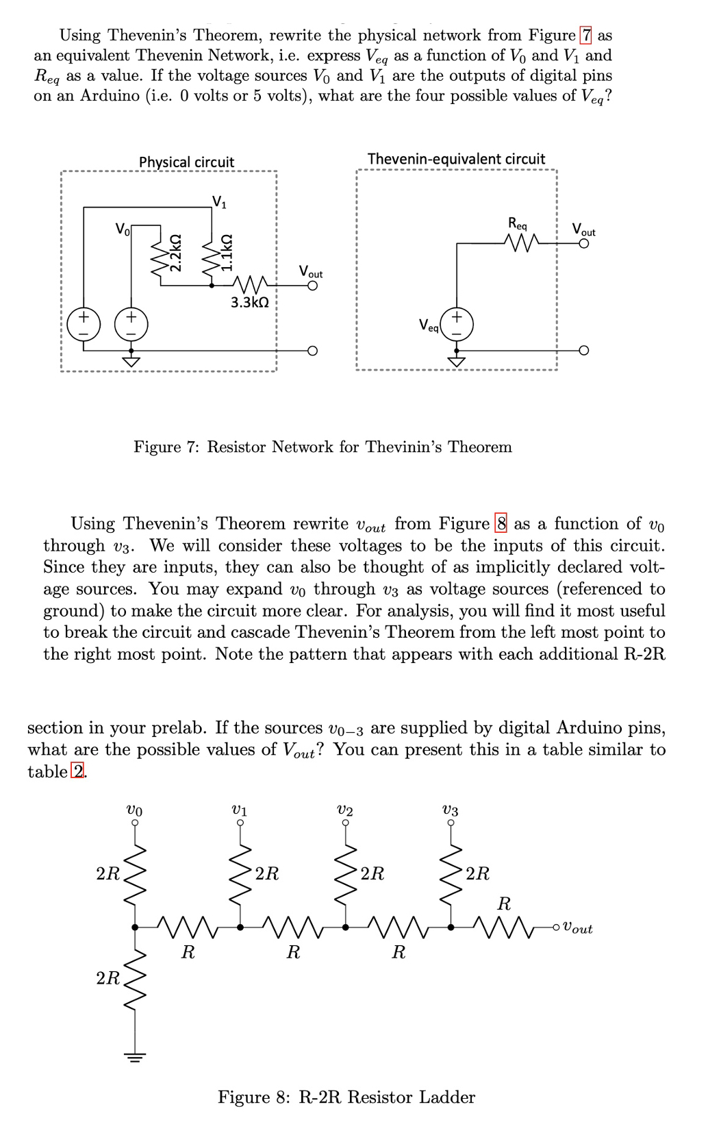

Transcribed Image Text:Using Thevenin's Theorem, rewrite the physical network from Figure 7 as
an equivalent Thevenin Network, i.e. express Veq as a function of V₁ and V₁ and
Req as a value. If the voltage sources Vo and V₁ are the outputs of digital pins
on an Arduino (i.e. 0 volts or 5 volts), what are the four possible values of Veq?
+
Vol
+
2R
Physical circuit
2R
VO
m
3.3ΚΩ
m
t
Figure 7: Resistor Network for Thevinin's Theorem
Using Thevenin's Theorem rewrite Vout from Figure 8 as a function of vo
through v3. We will consider these voltages to be the inputs of this circuit.
Since they are inputs, they can also be thought of as implicitly declared volt-
age sources. You may expand vo through v3 as voltage sources (referenced to
ground) to make the circuit more clear. For analysis, you will find it most useful
to break the circuit and cascade Thevenin's Theorem from the left most point to
the right most point. Note the pattern that appears with each additional R-2R
m
R
Vout
section in your prelab. If the sources vo-3 are supplied by digital Arduino pins,
what are the possible values of Vout? You can present this in a table similar to
table 2.
V1
2R
Thevenin-equivalent circuit
R
V2
Veg
♡
2R
R
Req
m
V3
2R
Vout
R
m
Figure 8: R-2R Resistor Ladder
- Vout
Expert Solution
This question has been solved!
Explore an expertly crafted, step-by-step solution for a thorough understanding of key concepts.

This is a popular solution

Trending nowThis is a popular solution!

Step by stepSolved in 3 steps with 2 images

Knowledge Booster


Learn more about
Need a deep-dive on the concept behind this application? Look no further. Learn more about this topic, electrical-engineering and related others by exploring similar questions and additional content below.Similar questions
- A 1) Consider the circuit at right, consisting of two LEDS (one red, one green), which you can model as “practical diodes" with VD= 2.0V (LEDS typically have larger VD's than ordinary Si or Ge diodes). R red green B a) If terminals A and B were connected to a DC source with voltage Vo, what would happen? (Consider applying in both polarities, i.e. +Vo and –Vo, and when VoVD...) b) If the terminals A and B were connected to an AC source with peak voltage VO, what would happen? (Consider both very low frequency: f<~1 Hz – and high-frequency cases.) c) If R = 1 k2, and both diodes have a maximum continuous power dissipation of 0.1 W and a peak inverse voltage VPIV = 20V, what is the maximum DC voltage VDCmax which can be safely applied between A and B?arrow_forwardAsP plzzzzarrow_forward
Recommended textbooks for you
- Introductory Circuit Analysis (13th Edition)Electrical EngineeringISBN:9780133923605Author:Robert L. BoylestadPublisher:PEARSON
 Delmar's Standard Textbook Of ElectricityElectrical EngineeringISBN:9781337900348Author:Stephen L. HermanPublisher:Cengage Learning
 Programmable Logic ControllersElectrical EngineeringISBN:9780073373843Author:Frank D. PetruzellaPublisher:McGraw-Hill Education
  Fundamentals of Electric CircuitsElectrical EngineeringISBN:9780078028229Author:Charles K Alexander, Matthew SadikuPublisher:McGraw-Hill Education
 Electric Circuits. (11th Edition)Electrical EngineeringISBN:9780134746968Author:James W. Nilsson, Susan RiedelPublisher:PEARSON
 Engineering ElectromagneticsElectrical EngineeringISBN:9780078028151Author:Hayt, William H. (william Hart), Jr, BUCK, John A.Publisher:Mcgraw-hill Education,
Introductory Circuit Analysis (13th Edition)
Electrical Engineering
ISBN:9780133923605
Author:Robert L. Boylestad
Publisher:PEARSON
Delmar's Standard Textbook Of Electricity
Electrical Engineering
ISBN:9781337900348
Author:Stephen L. Herman
Publisher:Cengage Learning
Programmable Logic Controllers
Electrical Engineering
ISBN:9780073373843
Author:Frank D. Petruzella
Publisher:McGraw-Hill Education
Fundamentals of Electric Circuits
Electrical Engineering
ISBN:9780078028229
Author:Charles K Alexander, Matthew Sadiku
Publisher:McGraw-Hill Education
Electric Circuits. (11th Edition)
Electrical Engineering
ISBN:9780134746968
Author:James W. Nilsson, Susan Riedel
Publisher:PEARSON
Engineering Electromagnetics
Electrical Engineering
ISBN:9780078028151
Author:Hayt, William H. (william Hart), Jr, BUCK, John A.
Publisher:Mcgraw-hill Education,