Introductory Circuit Analysis (13th Edition)
13th Edition
ISBN: 9780133923605
Author: Robert L. Boylestad
Publisher: PEARSON
expand_more
expand_more
format_list_bulleted
Concept explainers
Question
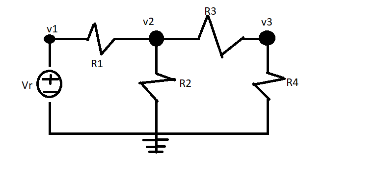
Using nodal analysis solve for v1,v2,v3 where the values of
Vr = 12V
R1= 5
R2 = 10
R3 = 15
R4 = 20

Expert Solution
arrow_forward
Introduction
The solution can be achieved as follows.
Trending nowThis is a popular solution!
Step by stepSolved in 2 steps with 1 images

Knowledge Booster
Learn more about
Need a deep-dive on the concept behind this application? Look no further. Learn more about this topic, electrical-engineering and related others by exploring similar questions and additional content below.Similar questions
- R1 ŽR4 + Vsi i6 R6 R2 iz is R5 Vs2 R3 iz Q9. In the circuit, Vs1 is 121 V, Vs2 is 130 V, R1 is 3 0hm, R2 is 6 0hm, R3 is 2 Ohm, R4 is 9 Ohm, R5 is 10 Ohm, R6 is 29 Ohm. Hint: When solving the circuit using nodal analysis, ground the node where Vs1(-), Vs2(+) and R2 are connected.arrow_forwardPLS SOLVE IT WITH A COMPLETE SOLUTION. SHOW HOW THE EQUATIONS REDUCE AS NEEDED.arrow_forwardUsing the circuit below, complete the table while showing your solutions and circuit simplifications. C1 = 1x10 HE F C3 =3x10¬°F H -6 F C5 = 5x10 C6 4x10¬º F = -6 2x10 ° F = C2 : C4 -6 = 6x10° F %3D 9x10⁻⁶ F = C9 Cg C, = 7x10 -6 F -6 = 8x10 F Ceq = Charge (C) Voltage (V) Q1 = Q2 = Q3 = Q4 = Q5 = Q6 = Q7 = Q8 = Qg = QT = V, = V2 = | V3 = V4 = V5 = V6 = V7 = V8 = V9 = AV = 24 Varrow_forward
- For the circuit below, use loop analysis to find the voltages VA, VB, and Vc: (Provide your calculations and reasoning for your answer.) Use matrix form to solve equatins. VA R10 R11 330 4k R13 470 VB Vc R8 R9 R12 1k 220 700 V3 V2 R15 R14 15Vdc 25Vde 2k 550 ww wwarrow_forwardVA For the following circuit, use nodal analysis to write the FOUR equations in standard form. DO NOT SOLVE. You must identify any quasi-supernodes, su- pernodes, auxiliary equations, and remove dependent variables. Your final equations may only have V1,V2,V3 and/or V4 as unknowns. Put your final equations in stan- dard form in the box provided. 12. )4A V2 Vi V3 8V +)3V Vo 5Varrow_forwardUsing nodal analysis for the circuit, write the nodal equation at V1 and at V2arrow_forward
- R3-50 Q UTM b) Figure Q4(b) is referred. By using nodal analysis, solve for: 5 UTM i) the values of voltage V, and V; in 5 UTM & UTM ii) the values of current, Ij in phasor domain and time domain UTM MS UTM 5 UTS 5 UTM 5 UTM 5 UTM & UTM 8 UTM 8 UTM 8 UTM 5 UTM 8 UTM 8 UTM R=10 Q UTM & UTM 8 UTM 8 UTM 8 U U XL=j5 Q 8 UTMSN 10020° v A 5 UTM 6 UTM R-20 Q R;=10 Q UTM 5 UTM M 8 UTM JUTM 8 UT 8 UTM 5 UM 8 UTM 5 UTM UTM UTM 8 UTM I-520° A UTM TM 8 UTM UTM 5 UTarrow_forwardDetermine the current and voltages using the circuit below . Put in polar and rectangular formarrow_forwardShown in the figure below is an electrical circuit containing three resistors and two batteries. R3 10 R2 R1 Write down the Kirchhoff Junction equation and solve it for I, in terms of I, and Iz. Write the result here: Write down the Kirchhoff Loop equation for a loop that starts at the lower left corner and follows the perimeter of the circuit diagram clockwise. Write down the Kirchhoff Loop equation for a loop that starts at the lower left corner and touches the components R1, R2, and 4V. The resistors in the circuit have the following values: R, = 130 • R2 = 50 R3 = 10 Solve for all the following (some answers may be negative): | Amperes I = I, = Amperes Iz = Amperes NOTE: For the equations, put in resistances and currents SYMBOLICALLY using variables like RR2,R3 and I,,12,13. Use numerical values of 10 and 4 for the voltages.arrow_forward
arrow_back_ios
arrow_forward_ios
Recommended textbooks for you
 Introductory Circuit Analysis (13th Edition)Electrical EngineeringISBN:9780133923605Author:Robert L. BoylestadPublisher:PEARSON
 Delmar's Standard Textbook Of ElectricityElectrical EngineeringISBN:9781337900348Author:Stephen L. HermanPublisher:Cengage Learning
 Programmable Logic ControllersElectrical EngineeringISBN:9780073373843Author:Frank D. PetruzellaPublisher:McGraw-Hill Education
 Fundamentals of Electric CircuitsElectrical EngineeringISBN:9780078028229Author:Charles K Alexander, Matthew SadikuPublisher:McGraw-Hill Education
 Electric Circuits. (11th Edition)Electrical EngineeringISBN:9780134746968Author:James W. Nilsson, Susan RiedelPublisher:PEARSON
 Engineering ElectromagneticsElectrical EngineeringISBN:9780078028151Author:Hayt, William H. (william Hart), Jr, BUCK, John A.Publisher:Mcgraw-hill Education,

Introductory Circuit Analysis (13th Edition)
Electrical Engineering
ISBN:9780133923605
Author:Robert L. Boylestad
Publisher:PEARSON

Delmar's Standard Textbook Of Electricity
Electrical Engineering
ISBN:9781337900348
Author:Stephen L. Herman
Publisher:Cengage Learning

Programmable Logic Controllers
Electrical Engineering
ISBN:9780073373843
Author:Frank D. Petruzella
Publisher:McGraw-Hill Education

Fundamentals of Electric Circuits
Electrical Engineering
ISBN:9780078028229
Author:Charles K Alexander, Matthew Sadiku
Publisher:McGraw-Hill Education

Electric Circuits. (11th Edition)
Electrical Engineering
ISBN:9780134746968
Author:James W. Nilsson, Susan Riedel
Publisher:PEARSON

Engineering Electromagnetics
Electrical Engineering
ISBN:9780078028151
Author:Hayt, William H. (william Hart), Jr, BUCK, John A.
Publisher:Mcgraw-hill Education,