Introductory Circuit Analysis (13th Edition)
13th Edition
ISBN: 9780133923605
Author: Robert L. Boylestad
Publisher: PEARSON
expand_more
expand_more
format_list_bulleted
Concept explainers
Question
thank you !

Transcribed Image Text:### Superposition Theorem in Electrical Circuits
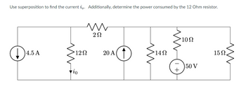
**Objective:** Use superposition to find the current \(i_0\). Additionally, determine the power consumed by the 12 Ohm resistor.
#### Circuit Description:
The circuit comprises:
- A 4.5 A current source.
- A 12Ω resistor.
- A 2Ω resistor.
- A 20 A current source.
- A 14Ω resistor.
- A 10Ω resistor.
- A 15Ω resistor.
- A 50 V voltage source.
These components are arranged as follows:
1. The 4.5 A current source is in series with the 12Ω resistor and the 2Ω resistor.
2. A 20 A current source is parallel to the series combination of the 4.5 A current source and the 2Ω resistor.
3. This combination is further in series with a 14Ω resistor which is parallel to a network containing a 10Ω resistor, a 50 V voltage source, and a 15Ω resistor.
The main objective is to determine the current \(i_0\) passing through the 12Ω resistor using the superposition technique and then find the power consumed by that resistor.
### Steps to Solve Using Superposition:
1. **Superposition Principle**:
- Temporarily remove all but one source (voltage and current sources) and solve the circuit.
- Repeat for each source.
- Combine the effects to get the total current \(i_0\).
2. **Removing Sources One at a Time**:
- Replace each independent voltage source with a short circuit (wire).
- Replace each independent current source with an open circuit (break).
3. **Calculating the Current \(i_0\)**:
- Open circuit the 20A current source and short circuit the 50V voltage source. Solve for \(i_0\) using the 4.5 A current source.
- Repeat the process for the other sources (one at a time).
- Superimpose the results.
4. **Determine Power Consumption**:
- Power consumed by the 12Ω resistor can be determined using \(P = i_0^2 \times R\).
### Graphical Representation:
- **Circuit Diagram**: The provided diagram represents the electrical circuit with components as described, with specified values of current and voltage sources and resistances.
#### Solving the Circuit:
Detailed
Expert Solution
This question has been solved!
Explore an expertly crafted, step-by-step solution for a thorough understanding of key concepts.
This is a popular solution
Trending nowThis is a popular solution!
Step by stepSolved in 6 steps with 26 images

Knowledge Booster
Learn more about
Need a deep-dive on the concept behind this application? Look no further. Learn more about this topic, electrical-engineering and related others by exploring similar questions and additional content below.Similar questions
- 1-Calculate the minimum and maximum protection for an A/C , its conductors(75 ºC) and its grounding. For the following values:1- FLC compressor = 30 A2- FLC condenser = 3 Aarrow_forwardWhat kind of cable uses BNC connectors?arrow_forwardWe are running 3 wires in an IMC to a control panel with a 150 amp circuit breaker disconnect in the control panel. The conduit is run 12 inches above the roof on a strut rack. The ambient air temperature is 88 degrees. This control panel feeds the #1 cooling fan. What sized ungrounded conductors do we need? All conductors have typeTHHN insulation. A #1 AWG B 100 Kcmil C #1/0 AWG D #10 AWG What sized IMC do we need? A 3/4" B 1 1/4" C 1" D 1 1/2"arrow_forward
- Explain each option & Choose the correct option. 4) The _ calculated load is rarely placed on an electrical system.A. optionalB. standardC. total 5) What's the primary disadvantage of using copper conductors?A. CostB. AvailabilityC. Weight 6) You're evaluating the components of a multioccupancy building that won't have an on-site employee. To be compliant with the NEC, each occupant will need to have access to their ownA. service-disconnecting means.B. service conductor.C. cable attachment point.D. emergency fire water pump disconnect ..arrow_forward16. The total voltage in a series-parallel circuit is __________ equal to the sum of the voltage drops across each resistor in the circuit. distributed across each branch in the circuit. determined by the product-over-sum method. equal to the voltage drop of the parallel branch. Which of the following statement is true both for a series and a parallel DC circuit? powers are additive voltages are additive currents are additive elements have individual currents Electric power is the ________ same as electric pressure. total number of electrons flowing in a circuit. number of electrons passing a given point in one second. rate of using or producing electric energy. A battery produces a current of 0.6 A when the external resistance is 2 ? and 0.2 A when the external resistance is 12 ?. Find the emf of the battery 3 V 6 V 9 V 12 Varrow_forward
arrow_back_ios
arrow_forward_ios
Recommended textbooks for you
 Introductory Circuit Analysis (13th Edition)Electrical EngineeringISBN:9780133923605Author:Robert L. BoylestadPublisher:PEARSON
 Delmar's Standard Textbook Of ElectricityElectrical EngineeringISBN:9781337900348Author:Stephen L. HermanPublisher:Cengage Learning
 Programmable Logic ControllersElectrical EngineeringISBN:9780073373843Author:Frank D. PetruzellaPublisher:McGraw-Hill Education
 Fundamentals of Electric CircuitsElectrical EngineeringISBN:9780078028229Author:Charles K Alexander, Matthew SadikuPublisher:McGraw-Hill Education
 Electric Circuits. (11th Edition)Electrical EngineeringISBN:9780134746968Author:James W. Nilsson, Susan RiedelPublisher:PEARSON
 Engineering ElectromagneticsElectrical EngineeringISBN:9780078028151Author:Hayt, William H. (william Hart), Jr, BUCK, John A.Publisher:Mcgraw-hill Education,

Introductory Circuit Analysis (13th Edition)
Electrical Engineering
ISBN:9780133923605
Author:Robert L. Boylestad
Publisher:PEARSON

Delmar's Standard Textbook Of Electricity
Electrical Engineering
ISBN:9781337900348
Author:Stephen L. Herman
Publisher:Cengage Learning

Programmable Logic Controllers
Electrical Engineering
ISBN:9780073373843
Author:Frank D. Petruzella
Publisher:McGraw-Hill Education

Fundamentals of Electric Circuits
Electrical Engineering
ISBN:9780078028229
Author:Charles K Alexander, Matthew Sadiku
Publisher:McGraw-Hill Education

Electric Circuits. (11th Edition)
Electrical Engineering
ISBN:9780134746968
Author:James W. Nilsson, Susan Riedel
Publisher:PEARSON

Engineering Electromagnetics
Electrical Engineering
ISBN:9780078028151
Author:Hayt, William H. (william Hart), Jr, BUCK, John A.
Publisher:Mcgraw-hill Education,