Related questions
Question
thumb_up100%
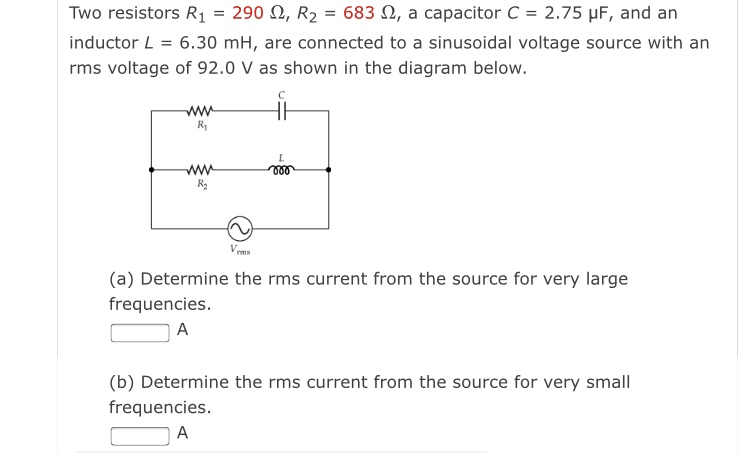

Transcribed Image Text:Two resistors R1 = 290 N, R2
683 N, a capacitor C = 2.75 µF, and an
inductor L = 6.30 mH, are connected to a sinusoidal voltage source with an
rms voltage of 92.0 V as shown in the diagram below.
ww
R1
ww
ll
Vrms
(a) Determine the rms current from the source for very large
frequencies.
A
(b) Determine the rms current from the source for very small
frequencies.
A
Expert Solution
This question has been solved!
Explore an expertly crafted, step-by-step solution for a thorough understanding of key concepts.

Step by stepSolved in 3 steps with 2 images

Knowledge Booster

Similar questions
- you have a series RLC cir cuit made witha Resistor R=43-0 r, indactor L=27:0 MH, and capacibor C= 16-0nF. The Circuit is ariven by an AC source with Vems = 15.0V at Frequency f=7-90 KHZ- what is the RMS Voltage Ni across the inductor ? what is the RMS voltage AVC across the capacitor? %3Darrow_forwardWhat capacitance is needed in a series with an 750-µH inductor to form a circuit that radiates a wavelength of 255 m? pFarrow_forwardA 83.0-mH inductor and a 7.10-μF capacitor are connected in series with a generator whose frequency is 414 Hz. The rms voltage across the capacitor is 1.60 V. Determine the rms voltage across the inductor.arrow_forward
- What is the magnitude of the impedance Z between nodes A and B with a resistance of R, a capacitance of C, and an inductance of L with the following values: w = 3600 rad/s, R = 50 M, L = 2.0 × 10⁻⁸ H, C = 12 μF. A ww reler Barrow_forwardThe figure below shows a series RLC circuit with a 26.0-N resistor, a 440.0-mH inductor, and a 28.0-µF capacitor connected to an AC source with Vmax = 60.0 V operating at 60.0 Hz. What is the maximum voltage across the following in the circuit? VR VL ll L C (a) resistor V (b) inductor V (c) capacitor Varrow_forwardIn an RLC circuit a second capacitor is addedin series to the capacitor already present. (a) Does the resonancefrequency increase, decrease, or stay the same? (b) Choose the bestexplanation from among the following:I. The resonance frequency stays the same because it dependsonly on the resistance in the circuit.II. Adding a capacitor in series increases the equivalent capacitance, and this decreases the resonance frequency.III. Adding a capacitor in series decreases the equivalent capacitance, and this increases the resonance frequency.arrow_forward
- At what frequency (in Hz) are the reactances of a 55- mH inductor and a 85-µF capacitor equal? Number Unitsarrow_forwardTwo resistors R1 = 323 N, R2 = 627 N, a capacitor C = 2.75 µF, and an inductor L = 6.30 mH, are connected to a sinusoidal voltage source with an rms voltage of 92.0 V as shown in the diagram below. ww R1 L ll R2 V. rms (a) Determine the rms current from the source for very large frequencies. A (b) Determine the rms current from the source for very small frequencies. Aarrow_forwardA multimeter in an RL circuit records an rms current of 0.300 A and a 55.0-Hz rms generator voltage of 101 V. A wattmeter shows that the average power delivered to the resistor is 14.0 W. (a) Determine the impedance in the circuit. (b) Determine the resistance, R. Ω (c) Determine the inductance, L. Harrow_forward
arrow_back_ios
arrow_forward_ios