
Structural Analysis
6th Edition
ISBN: 9781337630931
Author: KASSIMALI, Aslam.
Publisher: Cengage,
expand_more
expand_more
format_list_bulleted
Related questions
Question
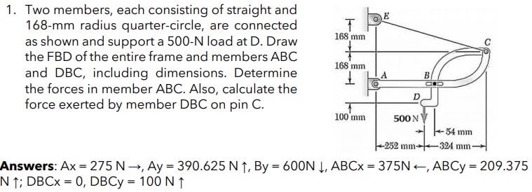

Transcribed Image Text:1. Two members, each consisting of straight and
168-mm radius quarter-circle, are connected
as shown and support a 500-N load at D. Draw
the FBD of the entire frame and members ABC
and DBC, including dimensions. Determine
the forces in member ABC. Also, calculate the
force exerted by member DBC on pin C.
E
168 mm
168 mm
B.
D.
100'mm
500 N
54 mm
-252 mm-
-324 mm
Answers: Ax = 275 N→, Ay = 390.625 N ↑, By = 600N Į, ABC× = 375N +, ABCY = 209.375
N ↑; DBC× = 0, DBCY = 100 N ↑
%3D
%3D
Expert Solution
This question has been solved!
Explore an expertly crafted, step-by-step solution for a thorough understanding of key concepts.

This is a popular solution

Trending nowThis is a popular solution!

Step by stepSolved in 2 steps with 2 images

Knowledge Booster


Learn more about
Need a deep-dive on the concept behind this application? Look no further. Learn more about this topic, civil-engineering and related others by exploring similar questions and additional content below.Similar questions
- y = EI 1 B For the beam and loading shown, determine Part 1 out of 3 (a) the equation of the elastic curve for portion AB of the beam, WO 2 L x Wo -L/2- 1 120 10 X X 1arrow_forwardEach of the links AB and CD is made of steel (E = 29 x 106 psi) and has a uniform 1 rectangular cross section of x 1 in. Determine the largest load which can be suspended from 4 point E if the deflection of E is not to exceed 0.02 in. 8 in. A 8 in. B O A 10 in. D 17 in. Earrow_forwardDetermine the force in Pin C for the frame shown. Frame comprises three members - AC, AB, and BD. Lengths are in meters. A B C D 20 40 N 12arrow_forward
- 8m A 6M using in F B с 100KN 8m 6m Method of Sections determine forces FE, FC, BCarrow_forwardA rigid ban AB and "CD" as shown are supported by pins at "A" & "C" and two ross. Determine the maximum force 'p' that can be applied as given if it's vertical movement is limited to 5 mm. Neglect the weight of all the members. www A 3m 3m Aluminium P L = 2m, A= 500m² E =70 GPA 3m IB 3m Steel L=2m A= 300m² E = 2006/ Darrow_forwardThe figure shows a roof truss and the detail of the connection at joint B. Members BC and BE are angle sections with the thickness shown in the figure. The working stresses are 70MPa for shear in the rivets and 140MPa for bearing stress due to the rivets. How many 22mm diameter rivets are required to fasten the following members to the gusset plate: (a) BC; and (b) BE? 000 4 m B с 96 kN D 6 m E 200 KN 4 m F G 4 m 96 kN H to- PBC - -14-mm-thick gusset plate -13-mm-thick angle 6-mm-thick angle PBEarrow_forward
- Problem 2: Determine the force in ALL the members of the truss. State if the members are in tension or compression. Show all your work to receive full credit. (Hint: It is not needed to find the reaction forces at C and E if you use the Method of Joints). Note: P1= 1000 lb and P: = 500 lb B C30 45 999 4 ft E 550 D. -4 ft- - 4 ft- 999 299arrow_forwardMember ACDF is a rigid bar. Links BC and DE are made of steel (E = 29,000 ksi) and are ½/2" wide and ¼" thick. If the applied force P is 1000 lb, what is the force in each of the links and the deflection of point A? B -4 in. D F 4 in. 2 in. 2 in -5 in.- 2210arrow_forward
arrow_back_ios
arrow_forward_ios
Recommended textbooks for you
 Structural Analysis (10th Edition)Civil EngineeringISBN:9780134610672Author:Russell C. HibbelerPublisher:PEARSON
 Principles of Foundation Engineering (MindTap Cou...Civil EngineeringISBN:9781337705028Author:Braja M. Das, Nagaratnam SivakuganPublisher:Cengage Learning
 Fundamentals of Structural AnalysisCivil EngineeringISBN:9780073398006Author:Kenneth M. Leet Emeritus, Chia-Ming Uang, Joel LanningPublisher:McGraw-Hill Education
 Traffic and Highway EngineeringCivil EngineeringISBN:9781305156241Author:Garber, Nicholas J.Publisher:Cengage Learning
Structural Analysis (10th Edition)
Civil Engineering
ISBN:9780134610672
Author:Russell C. Hibbeler
Publisher:PEARSON
Principles of Foundation Engineering (MindTap Cou...
Civil Engineering
ISBN:9781337705028
Author:Braja M. Das, Nagaratnam Sivakugan
Publisher:Cengage Learning
Fundamentals of Structural Analysis
Civil Engineering
ISBN:9780073398006
Author:Kenneth M. Leet Emeritus, Chia-Ming Uang, Joel Lanning
Publisher:McGraw-Hill Education
Traffic and Highway Engineering
Civil Engineering
ISBN:9781305156241
Author:Garber, Nicholas J.
Publisher:Cengage Learning