International Edition---engineering Mechanics: Statics, 4th Edition
4th Edition
ISBN: 9781305501607
Author: Andrew Pytel And Jaan Kiusalaas
Publisher: CENGAGE L
expand_more
expand_more
format_list_bulleted
Concept explainers
Question
Translate question.
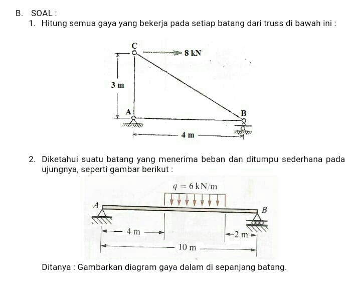
1. Calculate all the forces acting on each bar from the truss below.
2. Known a bar that receives a load and is supported simply at the end as shown below.
Asked: draw a force diagram along the stem

Expert Solution
This question has been solved!
Explore an expertly crafted, step-by-step solution for a thorough understanding of key concepts.
Step by stepSolved in 6 steps with 17 images

Knowledge Booster
Learn more about
Need a deep-dive on the concept behind this application? Look no further. Learn more about this topic, mechanical-engineering and related others by exploring similar questions and additional content below.Similar questions
- The following figure (5.12 from the text) shows a truss with several zero force members. Identify the seven (7) zero force members in the following list. Hint: make many passes through the truss. Once you find one zero force member you'll find more. Hint 2: You don't need to determine the magnitudes of the reactions, but you do need to determine if any of them are zero. 4 m 4 m 4 m. IF G 3 m 3 m B 40 kN 80 kN K 3 m A 4 m АК AL BJ BK CD СЕ CJ DE EJ FG FI HI O O O O 00000 O O0arrow_forwardDraw the Free Body Diagram Solve step by step Always used 3 decimal places! Thank you in advancearrow_forward-11 in-- 11 in-- 30 in E The sign with weight W, = 32 lb acts through it Center of Gravity as shown. The structural system is supported by pin connections at E and D. Define force directions with arrows for all problems. 30 20 (a) Calculate the magnitude of the tension force existing in member AE. Ski Reintals (b) Calculate the magnitude and direction of the vertical component of the reaction at D. (c) Calculate the magnitude and direction of the horizontal component of the reaction at D. 33 inarrow_forward
- For the next Trusses, compute the axial forces in the selected sections. Compare the result with the method of joints. (Check the image for the trusses)arrow_forward1. Please help me answer this mech. engineering question. Also please help me determine the force in CF and GFarrow_forwardProblem 1 For the frame loaded as shown, determine all the forces on members AD and ABC. Support at C is a roller. Hint: Please be careful in this problem: at point A, there are three elements connected at A: a pin A that is connected to ground (so, two support reactions due to that, say Ax and Ay), then, bar AD (two more reactions at A due to bar AD: call these as Ax_prime, and Ay_prime) and the bar AC (two more reactions at A due to bar AC: call these as Ax_doubleprime, Ay_doubleprime). So, you will need to draw a pin FBD at A showing all the six forces. 200 N 130 mm 400 mm V400 N A B -400 mm 400 mmarrow_forward
- m 4: The maximum force any member can support is 24 kN in tension and 35 kN in compression, determine the largest permissible mass "m" which may be supported by the truss. Hint: use the method of joints to calculate all of the member forces in terms of the weight (say "w"); then choose the largest positive and negative member forces to determine m = w/g. There is a "rocker" support at "E"; this is the same as a roller support. A E 4 m B D 4 m 30° marrow_forwardFind the internal forces in members BC, CG, and EG. Indicate whether it is tension or compression. Use method-of-sections. 1000 Ib 1000 Ib 500 Ib 20in 20in 20in 20inarrow_forwardPlease help with this practice question. Thanks Question 2) Determine the magnitude of the x-component of force at pin D. (The Units is kN)arrow_forward
- The connected pipes are attached to the wall with a fixed support; i.e. built in. Calculate the reaction forces due to the loading shown. FBD required, can be more sketch like, but must have all reactions drawn and labeled.The 150 N force is parallel to the z axis; −150 k', the 200 N force is parallel to the y axis; 200 j,̂I will assume that all of the moment support reactions(curved arrows) are drawn positive.arrow_forwardCan someone please help me to answer the following question and draw all free body diagrams and equivalent load diagrams.arrow_forwardCalculate the forces in all members of the truss shown in the following figure and mark the force values in every member. (All horizontal and vertical members are 1m long). 10 kN n o 10 KNarrow_forward
arrow_back_ios
SEE MORE QUESTIONS
arrow_forward_ios
Recommended textbooks for you
 International Edition---engineering Mechanics: St...Mechanical EngineeringISBN:9781305501607Author:Andrew Pytel And Jaan KiusalaasPublisher:CENGAGE L

International Edition---engineering Mechanics: St...
Mechanical Engineering
ISBN:9781305501607
Author:Andrew Pytel And Jaan Kiusalaas
Publisher:CENGAGE L