
Related questions
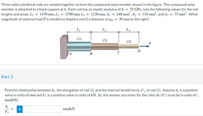
Three solid cylindrical rods are welded together to form the compound axial member shown in the figure. The compound axial member is attached to a fixed support at A. Each rod has an elastic modulus of E=35E=35 GPaGPa. Use the following values for the rod lengths and areas: L1=1470L1=1470 mmmm, L2=1590L2=1590 mmmm, L3=1230L3=1230 mmmm, A1=240A1=240 mm2mm2, A2=110A2=110 mm2mm2, and A3=75A3=75 mm2mm2. What magnitude of external load PP is needed to displace end D a distance of uD=30uD=30 mmmm to the right?
Find the relationship between δ1δ1, the elongation of rod (1), and the internal tensile force, F1F1, in rod (1). Assume δ1δ1 is a positive value in units of mmmm and F1F1 is a positive value in units of kNkN. So, the answer you enter for the ratio (δ1/F1δ1/F1) must be in units of (mm/kNmm/kN).
Hint: The length, cross-sectional area, and modulus of elasticity for rod (1) are all given.


Trending nowThis is a popular solution!

Step by stepSolved in 3 steps


- 7 ft 5 ft The assembly shown above includes column AB, which has the following properties: Pinned (top and bottom) for buckling about x-axis Free at top and fixed at bottom for buckling about y-axis Circular cross-section with 8-inch diameter E = 10000 ksi Which of the following is closest to the critical buckling force of column AB? O Per = 269 kip O Per = 1080 kip O Per = 538 kip O Per = 135 kiparrow_forwardAxial loads are applied with rigid bearing plates to the solid cylindrical rods shown in the figure. One load of P=33P=33 kipskips is applied to the assembly at A, two loads of Q=30Q=30 kipskips are applied at B, and two loads of R=35R=35 kipskips are applied at C. The normal stress magnitude in aluminum rod (1) must be limited to 1717 ksiksi. The normal stress magnitude in steel rod (2) must be limited to 3030 ksiksi. The normal stress magnitude in brass rod (3) must be limited to 2121 ksiksi. Determine the minimum diameter required for each of the three rods.arrow_forwardA vertical load P is applied at the center B of the upper section of a homogeneous frustum of a circular cone of length L, minimum radius rB, and maximum radius rA, as shown in the figure below. It is made of a material with a modulus of elasticity E. Neglect the effect of its weight. Use the following values: rA = 2 in, rB = 0.5 in, L = 3 ft, E = 30 (103 ) ksi, and P = 1800 lbf. Discretize the original geometry into three equal-length finite elements and (a) Compute all the nodal displacements. (b) Compute all the element axial stresses. (c) Plot the displacement field from the finite element method solution. (d) Plot the axial stress field from the finite element method solution.arrow_forward
- Elements Of ElectromagneticsMechanical EngineeringISBN:9780190698614Author:Sadiku, Matthew N. O.Publisher:Oxford University Press
 Mechanics of Materials (10th Edition)Mechanical EngineeringISBN:9780134319650Author:Russell C. HibbelerPublisher:PEARSON
 Thermodynamics: An Engineering ApproachMechanical EngineeringISBN:9781259822674Author:Yunus A. Cengel Dr., Michael A. BolesPublisher:McGraw-Hill Education
  Control Systems EngineeringMechanical EngineeringISBN:9781118170519Author:Norman S. NisePublisher:WILEY
 Mechanics of Materials (MindTap Course List)Mechanical EngineeringISBN:9781337093347Author:Barry J. Goodno, James M. GerePublisher:Cengage Learning
 Engineering Mechanics: StaticsMechanical EngineeringISBN:9781118807330Author:James L. Meriam, L. G. Kraige, J. N. BoltonPublisher:WILEY