
Introductory Circuit Analysis (13th Edition)
13th Edition
ISBN: 9780133923605
Author: Robert L. Boylestad
Publisher: PEARSON
expand_more
expand_more
format_list_bulleted
Related questions
Question
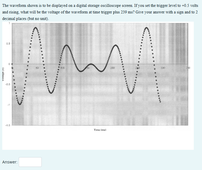

Transcribed Image Text:The waveform shown is to be displayed on a digital storage oscilloscope screen. If you set the trigger level to +0.5 volts
and rising, what will be the voltage of the waveform at time trigger plus 239 ms? Give your answer with a sign and to 2
decimal places (but no unit).
1
voltage (V)
0.5
-0.5
-1.5
Answer:
100
m
50
200
Time (ms)
300
350
Expert Solution
This question has been solved!
Explore an expertly crafted, step-by-step solution for a thorough understanding of key concepts.

Step by stepSolved in 3 steps with 2 images

Knowledge Booster


Learn more about
Need a deep-dive on the concept behind this application? Look no further. Learn more about this topic, electrical-engineering and related others by exploring similar questions and additional content below.Similar questions
- An analog or digital meter displays what quality of voltage or current in AC? (A) Peak (B)Average(C) RMS (D)Peak-to-peak (E)Instantaneousarrow_forwardA square wave that is 13 V at its on state and 0 V at its off state will produce an average DC voltage of _____ when it's duty cycle is 67%. Round your answer to 2 decimal placesarrow_forwardChanging the Volts/Div setting on an oscilloscope will: a change the actual period of the waveform. change the actual voltage level of the waveform. have no effect on the actual voltage level, period or frequency of the c) waveform. Cd change the actual frequency of the waveform.arrow_forward
- What did you observe on the output waveform (PR2) compare to the input waveform (PR1)? What type of clipper does circuit 1 depicts? Explain your answerarrow_forwardThe waveform displayed on an oscilloscope is as shown in Figure The 'time/cm' switch is set to 10 ms/cm, and the 'volts/cm' switch is set to 50 V/cm. Determine the (i) amplitude of waveform Q, (ii) peak to peak value of waveform P, (iii) frequency of waveform P and (iv) phase angle difference between P and Q in Degrees. Qarrow_forwardI need help on this onarrow_forward
arrow_back_ios
arrow_forward_ios
Recommended textbooks for you
- Introductory Circuit Analysis (13th Edition)Electrical EngineeringISBN:9780133923605Author:Robert L. BoylestadPublisher:PEARSON
 Delmar's Standard Textbook Of ElectricityElectrical EngineeringISBN:9781337900348Author:Stephen L. HermanPublisher:Cengage Learning
 Programmable Logic ControllersElectrical EngineeringISBN:9780073373843Author:Frank D. PetruzellaPublisher:McGraw-Hill Education
  Fundamentals of Electric CircuitsElectrical EngineeringISBN:9780078028229Author:Charles K Alexander, Matthew SadikuPublisher:McGraw-Hill Education
 Electric Circuits. (11th Edition)Electrical EngineeringISBN:9780134746968Author:James W. Nilsson, Susan RiedelPublisher:PEARSON
 Engineering ElectromagneticsElectrical EngineeringISBN:9780078028151Author:Hayt, William H. (william Hart), Jr, BUCK, John A.Publisher:Mcgraw-hill Education,
Introductory Circuit Analysis (13th Edition)
Electrical Engineering
ISBN:9780133923605
Author:Robert L. Boylestad
Publisher:PEARSON
Delmar's Standard Textbook Of Electricity
Electrical Engineering
ISBN:9781337900348
Author:Stephen L. Herman
Publisher:Cengage Learning
Programmable Logic Controllers
Electrical Engineering
ISBN:9780073373843
Author:Frank D. Petruzella
Publisher:McGraw-Hill Education
Fundamentals of Electric Circuits
Electrical Engineering
ISBN:9780078028229
Author:Charles K Alexander, Matthew Sadiku
Publisher:McGraw-Hill Education
Electric Circuits. (11th Edition)
Electrical Engineering
ISBN:9780134746968
Author:James W. Nilsson, Susan Riedel
Publisher:PEARSON
Engineering Electromagnetics
Electrical Engineering
ISBN:9780078028151
Author:Hayt, William H. (william Hart), Jr, BUCK, John A.
Publisher:Mcgraw-hill Education,