
International Edition---engineering Mechanics: Statics, 4th Edition
4th Edition
ISBN: 9781305501607
Author: Andrew Pytel And Jaan Kiusalaas
Publisher: CENGAGE L
expand_more
expand_more
format_list_bulleted
Related questions
Question
6
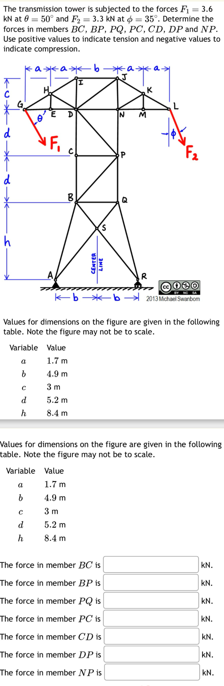

Transcribed Image Text:The transmission tower is subjected to the forces F₁ = 3.6
KN at = 50° and F2 = 3.3 kN at 6 = 35°. Determine the
forces in members BC, BP, PQ, PC, CD, DP and NP.
Use positive values to indicate tension and negative values to
indicate compression.
кажажь жажах
↑
d
d
h
K
L
N
M
IF,
P
B
Q
CENTER
LINE
R
Cc ④
BY NC SA
kbb 2013 Michael Swanbom
Values for dimensions on the figure are given in the following
table. Note the figure may not be to scale.
Variable
Value
1.7 m
a
b
4.9 m
C
3 m
d
5.2 m
h
8.4 m
Values for dimensions on the figure are given in the following
table. Note the figure may not be to scale.
Variable
a
Value
1.7 m
b
4.9 m
3 m
с
d
5.2 m
h
8.4 m
The force in member BC is
The force in member BP is
The force in member PQ is
The force in member PC is
The force in member CD is
The force in member DP is
The force in member NP is
KN.
KN.
KN.
KN.
KN.
KN.
KN.
į į į į Ź Ź Ź
Expert Solution
This question has been solved!
Explore an expertly crafted, step-by-step solution for a thorough understanding of key concepts.

Step by stepSolved in 2 steps with 4 images

Knowledge Booster

Similar questions
- Problem 3 - Determine whether the block shown is in equilibrium. Find the magnitude and direction of the friction force. Ms=0.30 MK=0.20 400 N 300N 130 45°arrow_forwardG -4 ft- AF FE Вс AB Gx Ax FC AF B Select the freebody diagram that would allow you to solve for the force FE using only that FBD if P1 = 2 kip and P2= 3 kip. GF P₁ Ay F BF E 2 Kip 2 кір 4 ft- B 4 ft- 4 ft- >CF ft B B 2 kip -4 ft- 2 Кір E EF P₁ 3Kip 4 ft- 4 ft E 2 кір 52 TFC -4 ft- FE zkip -4 ft Be 4 ft- экір 4 ft ID P₂ D экір 4 ft 4 ft inarrow_forwardNow that we've found the force F12, which equilibrium equation will allow us to find the force F13 between joint 1 and 3? Question 3 options: Sum of torques = 0 Sum of horizontal forces = 0 Sum of vertical forces = 0arrow_forward
- 200 N A block placed under the head, of the claw hammer as shown greatly facilitates the extraction of the nail. If the 200-N pull on the handle is required, to pull the nail calculate the tension T in the nail and the magnitude A of the force exerted by the hammer head on the block. The contacting surfaces at A are sufficiently rough to 200 mm 20 45 mm prevent slipping 1. 50- |Imm L->arrow_forwardThe transmission tower is subjected to the forces F = 8 kN at 0 = 54° and F2 = 5.7 kN at o = 31°. Determine the forces in members BC, BP, and PQ. Use positive values to indicate tension and negative values to indicate compression. ka*a b *a>*a H. K G D N d P F2 d B. Q h A, R cc BY NC SA kb * b> -6 2013 Michael Swanbom Values for dimensions on the figure are given in the following table. Note the figure may not be to scale. Variable Value 1.3 m 4.1 m 2.3 m 5.2 m 8.3 m h The force in member BC is kN. The force in member BP is kN. The force in member PQ is kN. CENTER LINEarrow_forwardAnswer should be Mf = 192..5 lbs and T=15.8lbarrow_forward
- Need help, round answers to 3 sig figs pleasearrow_forwardQ) Determine the tension in cables BA and BC necessary to support the 60 kg cylinder as shown in figure helow. , TBC Solution: Tecsin45 TRAsing 45 X. Ta:cos0 Taccos45 W = mg 53 W =mg = 60*9.81 = 588.6 N 0 = tan (3:4) = 37 Σ-0 Tục cos45 – TBAcos37 0 (1) EF, = 0 TBCsin45 + TBASin37- w 0arrow_forward3_8arrow_forward
- 6arrow_forwardA statically determinate truss is one of the early problems addressed in sophomore statics classes. A typical problem is shown in figure below: 2 Fapplied √30° F₁ F3 F2 02 3 L. Hinge Roller The applied force has a magnitude of 1000 N at an angle of 30° from the horizontal, as shown in the figure. The inner angles ₁ and 2 are 45° and 65° respectively. Determine the values of the forces in each member of the truss, and the reactive forces experienced at the hinge and the roller (nodes 2 and 3). Set up the problem using a simultaneous equation system. Use the method of the inverse matrix taught in the lectures. Follow the steps a) to e) as indicated below (assume "S" as the matrix representing the previous system. a) Calculate the matrix of minors of S. b) Calculate the matrix of cofactors of S (name it H) c) Calculate the determinant of S. d) Calculate the Adjoint of matrix of S using adj S = HT e) Calculate the inverse of matrix S using S₁ = adj S/|S|arrow_forwardno matter what calculaton I make I keep getting numbers that aren't even close to what they should be, can you help me figure out what I am missing with this?arrow_forward
arrow_back_ios
SEE MORE QUESTIONS
arrow_forward_ios
Recommended textbooks for you
- International Edition---engineering Mechanics: St...Mechanical EngineeringISBN:9781305501607Author:Andrew Pytel And Jaan KiusalaasPublisher:CENGAGE L
International Edition---engineering Mechanics: St...
Mechanical Engineering
ISBN:9781305501607
Author:Andrew Pytel And Jaan Kiusalaas
Publisher:CENGAGE L