Elements Of Electromagnetics
7th Edition
ISBN: 9780190698614
Author: Sadiku, Matthew N. O.
Publisher: Oxford University Press
expand_more
expand_more
format_list_bulleted
Concept explainers
Question

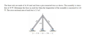
Transcribed Image Text:The three rods are made of A-36 steel and form a pin-connected truss as shown. The assembly is stress-
free at 50 °F. Determine the force in each bar when the temperature of the assembly is increased to 110
°F. The cross-sectional area of each bar is 2.5 in².
5 ft
4 ft
D
5 ft
3 ft 3ft
Expert Solution
This question has been solved!
Explore an expertly crafted, step-by-step solution for a thorough understanding of key concepts.
This is a popular solution
Trending nowThis is a popular solution!
Step by stepSolved in 6 steps with 5 images

Knowledge Booster
Learn more about
Need a deep-dive on the concept behind this application? Look no further. Learn more about this topic, mechanical-engineering and related others by exploring similar questions and additional content below.Similar questions
- Two solid cylindrical rods (1) and (2) are joined together at flange B and loaded as shown. If F₁ = 13 kips, F₂ = 34 kips, and the normal stress in each rod must be limited to 22 ksi, determine the minimum diameter d₁ required for rod (1). A (2) d₁ F₂ B C O 1.087 in. O 0.823 in. O 0.541 in. O 0.867 in. O 1.003 in. d₂arrow_forwardAt a temperature of 20 °C there is a gap ∆ = 0.2 mm between the lower end of the brass bar and the slab rigid suspended from the two steel bars. Neglecting the mass of the slab, determine the stress in each bar when the temperature of the assembly rises to 100°C Answer: σsteel = 15.462MPa (t), σbronze= 20.615MPa(c),arrow_forwardReview Part A The 50-mm-diameter cylinder is made from Am 1004-T61 magnesium and is placed in the clamp when the temperature is T = 20°C. (Figure 1) If the 304-stainless-steel carriage bolts of the clamp each have a diameter of 12 mm, and they hold the cylinder snug with negligible force against the rigid jaws, determine the force in the cylinder when the temperature rises to T2 = 130°C. Express your answer to three significant figures and include the appropriate units. HA F = 1301.4 Figure 1 of 1 Submit Previous Answers Request Answer 100 mm 150 mm Provide Feedback Next >arrow_forward
- Please show full solution please, thank youarrow_forwardP- 45° 45° Fig. 2-38arrow_forwardThe bars AB, AC, and AD are pinned together as shown in the Horizontal movement of the pin at A is prevented by the rigid horizontal strut AE. Calculate the axial force in the strut caused by the 10-kip load. For each steel bar, A = 0.3 in.2 and E = 29 x 106 psi. For the aluminum bar, A = 0.6 in.2 and E = 10 x 106 psi.arrow_forward
arrow_back_ios
arrow_forward_ios
Recommended textbooks for you
 Elements Of ElectromagneticsMechanical EngineeringISBN:9780190698614Author:Sadiku, Matthew N. O.Publisher:Oxford University Press
 Mechanics of Materials (10th Edition)Mechanical EngineeringISBN:9780134319650Author:Russell C. HibbelerPublisher:PEARSON
 Thermodynamics: An Engineering ApproachMechanical EngineeringISBN:9781259822674Author:Yunus A. Cengel Dr., Michael A. BolesPublisher:McGraw-Hill Education
 Control Systems EngineeringMechanical EngineeringISBN:9781118170519Author:Norman S. NisePublisher:WILEY
 Mechanics of Materials (MindTap Course List)Mechanical EngineeringISBN:9781337093347Author:Barry J. Goodno, James M. GerePublisher:Cengage Learning
 Engineering Mechanics: StaticsMechanical EngineeringISBN:9781118807330Author:James L. Meriam, L. G. Kraige, J. N. BoltonPublisher:WILEY

Elements Of Electromagnetics
Mechanical Engineering
ISBN:9780190698614
Author:Sadiku, Matthew N. O.
Publisher:Oxford University Press

Mechanics of Materials (10th Edition)
Mechanical Engineering
ISBN:9780134319650
Author:Russell C. Hibbeler
Publisher:PEARSON

Thermodynamics: An Engineering Approach
Mechanical Engineering
ISBN:9781259822674
Author:Yunus A. Cengel Dr., Michael A. Boles
Publisher:McGraw-Hill Education

Control Systems Engineering
Mechanical Engineering
ISBN:9781118170519
Author:Norman S. Nise
Publisher:WILEY

Mechanics of Materials (MindTap Course List)
Mechanical Engineering
ISBN:9781337093347
Author:Barry J. Goodno, James M. Gere
Publisher:Cengage Learning

Engineering Mechanics: Statics
Mechanical Engineering
ISBN:9781118807330
Author:James L. Meriam, L. G. Kraige, J. N. Bolton
Publisher:WILEY