
Introductory Circuit Analysis (13th Edition)
13th Edition
ISBN: 9780133923605
Author: Robert L. Boylestad
Publisher: PEARSON
expand_more
expand_more
format_list_bulleted
Related questions
Concept explainers
Question
thumb_up100%
Attached are the examples mentioned in the question below. These are examples from a textbook, not a graded exam or assignment so please do not reject.
Question: The synchronous machine of Examples 5.1 and 5.2 is to be operated as a synchronous generator.
For operation at 60 Hz with a terminal voltage of 460 V line-to-line, calculate the field current
required to supply a load of 85 kW, 0.95 power-factor leading.
given Solution:
46.3 A
Can someone explain how to reach this answer? I've tried to figure it out in several ways but the closest answer I got was 54.6 A.
Thank you!
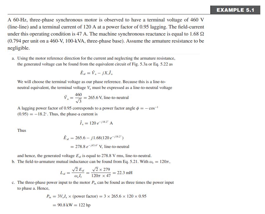

Transcribed Image Text:A 60-Hz, three-phase synchronous motor is observed to have a terminal voltage of 460 V
(line-line) and a terminal current of 120 A at a power factor of 0.95 lagging. The field-current
under this operating condition is 47 A. The machine synchronous reactance is equal to 1.68 2
(0.794 per unit on a 460-V, 100-kVA, three-phase base). Assume the armature resistance to be
negligible.
a. Using the motor reference direction for the current and neglecting the armature resistance,
the generated voltage can be found from the equivalent circuit of Fig. 5.3a or Eq. 5.22 as
Ê af = V₁ - jX₂Î₂
We will choose the terminal voltage as our phase reference. Because this is a line-to-
neutral equivalent, the terminal voltage V₂ must be expressed as a line-to-neutral voltage
460
265.6 V, line-to-neutral
V₂ =
A lagging power factor of 0.95 corresponds to a power factor angle = −cos-¹
(0.95) = -18.2°. Thus, the phase-a current is
Î₁ = 120 e-/18.2° A
Thus
Êt = 265.6-j1.68 (120 e-j¹8.2°)
af
= 278.8 e-43.40 V, line-to-neutral
and hence, the generated voltage Eaf is equal to 278.8 V rms, line-to-neutral.
b. The field-to-armature mutual inductance can be found from Eq. 5.21. With ₂ = 120,
√2 Eat
Lat
√2 x 279
120 x 47
22.3 mH
w.le
c. The three-phase power input to the motor Pin can be found as three times the power input
to phase a. Hence,
Pin = 3V₁I₁ x (power factor) = 3 x 265.6 x 120 x 0.95
= 90.8 kW = 122 hp
EXAMPLE 5.1

Transcribed Image Text:EXAMPLE 5.2
Assuming the input power and terminal voltage for the motor of Example 5.1 remain constant,
calculate (a) the phase angle & of the generated voltage and (b) the field current required to
achieve unity power factor at the motor terminals.
■ Solution
a. For unity power factor at the motor terminals, the phase-a terminal current will be in
phase with the phase-a line-to-neutral voltage V₁. Thus
From Eq. 5.22,
I₁ =
Pin
1₁ = =
3V₂
Êat = V₁-jX,Î.
= 265.6-j1.68 x 114 = 328 e
Thus, Euf = 328 V line-to-neutral and 8 = -35.8°.
√E
W.L.
90.6 kW
3 x 265.6 V
=
= 114 A
5.2 Synchronous-Machine Inductances; Equivalent Circuits
b. Having found L₁ in Example 5.1, we can find the required field current from Eq. 5.21.
√2 x 328
377 x 0.0223
-135.8
= 55.2 A
V₂, line-to-neutral
273
Expert Solution
This question has been solved!
Explore an expertly crafted, step-by-step solution for a thorough understanding of key concepts.

This is a popular solution

Trending nowThis is a popular solution!

Step by stepSolved in 3 steps with 2 images

Knowledge Booster


Learn more about
Need a deep-dive on the concept behind this application? Look no further. Learn more about this topic, electrical-engineering and related others by exploring similar questions and additional content below.Similar questions
- Suppose that the P-Q load is known at each of the nine buses of a small power system and that synchronous generators are connected to buses 1, 2, 5 & 7. For a power-flow study, identify the number of equations to be solved: Select one: O a. 15 b. 13 c. 11 d. None of these Oe. 9arrow_forwardSubject:machines topic: synchronous machinesarrow_forwardEnergy Question-1) Three identical synchronous generators were connected in parallel and the idle frequency values of each generator were set to 54 Hz. The frequency - power characteristic slopes of the first and second generators are 5.3 MW/Hz and the slope of the third generator is 3.9 MW/Hz. When these three identical synchronous generators feed a load together, the system frequency becomes f=51.7 Hz. According to this;a-) Calculate the active power value that the first generator will provide to the load.b-) Find the active power that the second generator will provide to the load.c-) Find the active power that the third generator will provide to the load.d-) Calculate the power of the load.(All values in options a, b, c, and d in this Question will be entered as two digits after the comma.) NOTE: If the information in the text and the photo is different, please solve the question using the information given in the photo. Help me please... Thank you so much.arrow_forward
Recommended textbooks for you
- Introductory Circuit Analysis (13th Edition)Electrical EngineeringISBN:9780133923605Author:Robert L. BoylestadPublisher:PEARSON
 Delmar's Standard Textbook Of ElectricityElectrical EngineeringISBN:9781337900348Author:Stephen L. HermanPublisher:Cengage Learning
 Programmable Logic ControllersElectrical EngineeringISBN:9780073373843Author:Frank D. PetruzellaPublisher:McGraw-Hill Education
  Fundamentals of Electric CircuitsElectrical EngineeringISBN:9780078028229Author:Charles K Alexander, Matthew SadikuPublisher:McGraw-Hill Education
 Electric Circuits. (11th Edition)Electrical EngineeringISBN:9780134746968Author:James W. Nilsson, Susan RiedelPublisher:PEARSON
 Engineering ElectromagneticsElectrical EngineeringISBN:9780078028151Author:Hayt, William H. (william Hart), Jr, BUCK, John A.Publisher:Mcgraw-hill Education,
Introductory Circuit Analysis (13th Edition)
Electrical Engineering
ISBN:9780133923605
Author:Robert L. Boylestad
Publisher:PEARSON
Delmar's Standard Textbook Of Electricity
Electrical Engineering
ISBN:9781337900348
Author:Stephen L. Herman
Publisher:Cengage Learning
Programmable Logic Controllers
Electrical Engineering
ISBN:9780073373843
Author:Frank D. Petruzella
Publisher:McGraw-Hill Education
Fundamentals of Electric Circuits
Electrical Engineering
ISBN:9780078028229
Author:Charles K Alexander, Matthew Sadiku
Publisher:McGraw-Hill Education
Electric Circuits. (11th Edition)
Electrical Engineering
ISBN:9780134746968
Author:James W. Nilsson, Susan Riedel
Publisher:PEARSON
Engineering Electromagnetics
Electrical Engineering
ISBN:9780078028151
Author:Hayt, William H. (william Hart), Jr, BUCK, John A.
Publisher:Mcgraw-hill Education,