
Elements Of Electromagnetics
7th Edition
ISBN: 9780190698614
Author: Sadiku, Matthew N. O.
Publisher: Oxford University Press
expand_more
expand_more
format_list_bulleted
Related questions
Concept explainers
Question
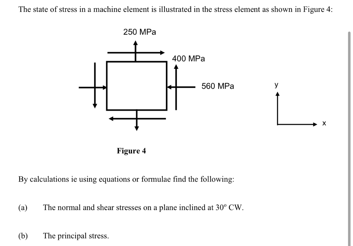

Transcribed Image Text:The state of stress in a machine element is illustrated in the stress element as shown in Figure 4:
(a)
(b)
250 MPa
Figure 4
By calculations ie using equations or formulae find the following:
The principal stress.
400 MPa
560 MPa
The normal and shear stresses on a plane inclined at 30° CW.
L.
Expert Solution
This question has been solved!
Explore an expertly crafted, step-by-step solution for a thorough understanding of key concepts.

This is a popular solution

Trending nowThis is a popular solution!

Step by stepSolved in 3 steps with 3 images

Knowledge Booster


Learn more about
Need a deep-dive on the concept behind this application? Look no further. Learn more about this topic, mechanical-engineering and related others by exploring similar questions and additional content below.Similar questions
- Calcuate torsion From Point A to Point C, Calcuate Bending From Point A to Point B and Point A to Point C. Draw a FBD from point A to point B and another for point A to C indicating what stresses are been calculate. Use the stress tensor and stress cube to Indicate what forces are acting at point A. Force apply at point B is 70lb Distacen from Point A to B is 12 in or 1 feet long Distacen from Point A to C is 3 in Handle diameter 0.625 inarrow_forwardQuestion 2 For the stresses of plane stress state is ox = -8 MPa , Oy = 7 MPa and Txy = -6 MPa Draw a Mohr's circle diagram. Draw stress element for the given stresses Find the principal normal and shear stresses, and determine the angle from the x axis to ơ1 Draw the stress element for the principle stress. Using stress transformation, find the principle stresses and the angle of o, Determine the stress transformation for the angle Ø = 25°arrow_forwardPlease work out part A and Barrow_forward
- Answer the questions below for the following system. Young's modulus and Poison's ratio can be taken as 200 GPa and 0.3, respectively. a) Calculate and determine the stress state for point H using undergraduate level solid mechanics knowledge? b) Determine the principal stress values at point H using undergraduate level solid mechanics knowledge? Top view of section where H is located Point H no 300 mm 120 mm C .H 540 mm A Diameter of the pipe d=36 mm P=900 Narrow_forwardEither all or none..arrow_forward(c) An element is subject to the stresses shown below in Figure 5 Calculate the centre and radius of the Mohr's stress circle and sketch the circle (1) (ii) Calculate the values of principal stresses and show them on the circle (ii) Determine the direction of the larger principal stress relative to the 75 N/mm. 30 N/mm A 14 Nmm 75 N/mm2 30 N/mm Figure 5arrow_forward
- Calcuate Shear and Bending From Point A to Point B and Point A to Point C. Draw a FBD from point A to point B and another for point A to C indicating what stresses are been calculate. Use the stress tensor and stress cube to Indicate what forces are acting at point A. Force apply at point B is 70lb Distacen from Point A to B is 12 in or 1 feet long Distacen from Point A to C is 3 in Handle diameter 0.625 inarrow_forwardFor the previous problem, compute the following six stress quantities: Ox, Oy, 0z, Txy, Tyz, Tzx. Assume this is an aluminum alloy (E = 10,000 ksi, G = 3800 ksi, v = 0.33). Do not forget units!arrow_forwardAn element is subject to the stresses shown below in Figure 5 (i) Calculate the centre and radius of the Mohr's stress circle and sketch the circle (ii) Calculate the values of principal stresses and show them on the circle (iii) Determine the direction of the larger principal stress relative to the 75 N/mm?. 30 N/mm? 14 N/mm? 75 N/mm? 75 N/mm? 30 N/mm2 Figure 5arrow_forward
- How would you solve thisarrow_forwardCalcuate torsion From Point A to Point C, Calcuate Bending From Point A to Point B and Point A to Point C. Draw a FBD from point A to point B and another for point A to C indicating what stresses are been calculate. Use the stress tensor and stress cube to Indicate what forces are acting at point A. Force apply at point B is 70lb Distacen from Point A to B is 12 in or 1 feet long Distacen from Point A to C is 3 in Handle diameter 0.625 inarrow_forwardProblem #2: The following tank presents the following data: • External diameter of 16 inches • ½ inch wall thickness • Internal Pressure 600 psi. 12 kip ft ! B 48 kip ft A 16 in. - p = 600 psi For point B, determine: a) The state of normal and shear stresses. b) The maximum and minimum efforts. Indicate the orientation of the principal axes c) The maximum shear stress. Indicate the orientation of the axes for this effortarrow_forward
arrow_back_ios
SEE MORE QUESTIONS
arrow_forward_ios
Recommended textbooks for you
- Elements Of ElectromagneticsMechanical EngineeringISBN:9780190698614Author:Sadiku, Matthew N. O.Publisher:Oxford University Press
 Mechanics of Materials (10th Edition)Mechanical EngineeringISBN:9780134319650Author:Russell C. HibbelerPublisher:PEARSON
 Thermodynamics: An Engineering ApproachMechanical EngineeringISBN:9781259822674Author:Yunus A. Cengel Dr., Michael A. BolesPublisher:McGraw-Hill Education
  Control Systems EngineeringMechanical EngineeringISBN:9781118170519Author:Norman S. NisePublisher:WILEY
 Mechanics of Materials (MindTap Course List)Mechanical EngineeringISBN:9781337093347Author:Barry J. Goodno, James M. GerePublisher:Cengage Learning
 Engineering Mechanics: StaticsMechanical EngineeringISBN:9781118807330Author:James L. Meriam, L. G. Kraige, J. N. BoltonPublisher:WILEY
Elements Of Electromagnetics
Mechanical Engineering
ISBN:9780190698614
Author:Sadiku, Matthew N. O.
Publisher:Oxford University Press
Mechanics of Materials (10th Edition)
Mechanical Engineering
ISBN:9780134319650
Author:Russell C. Hibbeler
Publisher:PEARSON
Thermodynamics: An Engineering Approach
Mechanical Engineering
ISBN:9781259822674
Author:Yunus A. Cengel Dr., Michael A. Boles
Publisher:McGraw-Hill Education
Control Systems Engineering
Mechanical Engineering
ISBN:9781118170519
Author:Norman S. Nise
Publisher:WILEY
Mechanics of Materials (MindTap Course List)
Mechanical Engineering
ISBN:9781337093347
Author:Barry J. Goodno, James M. Gere
Publisher:Cengage Learning
Engineering Mechanics: Statics
Mechanical Engineering
ISBN:9781118807330
Author:James L. Meriam, L. G. Kraige, J. N. Bolton
Publisher:WILEY