Elements Of Electromagnetics
7th Edition
ISBN: 9780190698614
Author: Sadiku, Matthew N. O.
Publisher: Oxford University Press
expand_more
expand_more
format_list_bulleted
Question
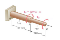
The solid shaft shown is formed of a brass for which the allowable shearing stress is 55 MPa. Neglecting the effect of stress concentrations, determine the smallest diameters dAB and dBC for which the allowable shearing stress is not exceeded. Take TC = 300 N·m.

Transcribed Image Text:### Torsion in a Shaft
The image illustrates a shaft subjected to torsional forces. Key elements include:
- **Points**:
- **A**: The starting point of the shaft, where it is fixed.
- **B**: The point at which a torque \( T_B = 1200 \, \text{N} \cdot \text{m} \) is applied.
- **C**: The end of the shaft where torque \( T_C \) is applied.
- **Distances**:
- \( d_{AB} = 750 \, \text{mm} \): The distance from point A to point B.
- \( d_{BC} = 600 \, \text{mm} \): The distance from point B to point C.
- **Torques**:
- \( T_B = 1200 \, \text{N} \cdot \text{m} \) is acting in a clockwise direction at point B.
- \( T_C \) is shown in a counterclockwise direction at point C.
This diagram represents how torques are applied along the length of a cylindrical shaft. Understanding the distribution and direction of these forces is essential in mechanical and structural engineering to prevent mechanical failures.
Expert Solution
This question has been solved!
Explore an expertly crafted, step-by-step solution for a thorough understanding of key concepts.
This is a popular solution
Trending nowThis is a popular solution!
Step by stepSolved in 2 steps with 2 images

Knowledge Booster
Similar questions
- 1. The member BD is attached to a rod at B, to a hydraulic cylinder at C, and to a fixed support at D. The bolt used at D acts in double shear and is made from a steel for which the maximum allowable shearing stress is Tallow = 40 ksi. The rod AB is made of a steel for which the maximum allowable tensile stress is Oallow = 60 ksi. The upward hydraulic force applied at C is 12 kip. 1) Calculate the minimum diameter of the rod AB. 2) Calculate the minimum diameter of the bolt at D. B FAB 12 kip 8 in. FBDarrow_forwardPravinbhaiarrow_forwardA torque T= 50 kip-in. is applied at end A of the composite shaft shown. Know that the modulus of rigidity is 11.2 x 10 psi for steel and 4 x 10⁶ psi for aluminum. 3 in. 24in. 100 in. Steel Aluminum Determine the maximum shearing stress in the steel core.arrow_forward
- For the state of plane stress shown, use Mohr’s circle to determine (a) the largest value of τxy for which the maximum in-plane shearing stress is equal to or less than 12 ksi, (b) the corresponding principal stresses.arrow_forwardUnder normal operating conditions, the electric motor exerts a torque of 2.4 kN·m on shaft AB. Each shaft is solid with diameter d 52 mm. In order to reduce the total mass of the assembly, a new design is being considered in which the diameter of shaft BC will be smaller. Determine the smallest diameter of shaft BC for which the maximum value of the shearing stress in the assembly will not be increased. The smallest diameter of shaft BC is mm.arrow_forward
arrow_back_ios
arrow_forward_ios
Recommended textbooks for you
 Elements Of ElectromagneticsMechanical EngineeringISBN:9780190698614Author:Sadiku, Matthew N. O.Publisher:Oxford University Press
 Mechanics of Materials (10th Edition)Mechanical EngineeringISBN:9780134319650Author:Russell C. HibbelerPublisher:PEARSON
 Thermodynamics: An Engineering ApproachMechanical EngineeringISBN:9781259822674Author:Yunus A. Cengel Dr., Michael A. BolesPublisher:McGraw-Hill Education
 Control Systems EngineeringMechanical EngineeringISBN:9781118170519Author:Norman S. NisePublisher:WILEY
 Mechanics of Materials (MindTap Course List)Mechanical EngineeringISBN:9781337093347Author:Barry J. Goodno, James M. GerePublisher:Cengage Learning
 Engineering Mechanics: StaticsMechanical EngineeringISBN:9781118807330Author:James L. Meriam, L. G. Kraige, J. N. BoltonPublisher:WILEY

Elements Of Electromagnetics
Mechanical Engineering
ISBN:9780190698614
Author:Sadiku, Matthew N. O.
Publisher:Oxford University Press

Mechanics of Materials (10th Edition)
Mechanical Engineering
ISBN:9780134319650
Author:Russell C. Hibbeler
Publisher:PEARSON

Thermodynamics: An Engineering Approach
Mechanical Engineering
ISBN:9781259822674
Author:Yunus A. Cengel Dr., Michael A. Boles
Publisher:McGraw-Hill Education

Control Systems Engineering
Mechanical Engineering
ISBN:9781118170519
Author:Norman S. Nise
Publisher:WILEY

Mechanics of Materials (MindTap Course List)
Mechanical Engineering
ISBN:9781337093347
Author:Barry J. Goodno, James M. Gere
Publisher:Cengage Learning

Engineering Mechanics: Statics
Mechanical Engineering
ISBN:9781118807330
Author:James L. Meriam, L. G. Kraige, J. N. Bolton
Publisher:WILEY