Introductory Circuit Analysis (13th Edition)
13th Edition
ISBN: 9780133923605
Author: Robert L. Boylestad
Publisher: PEARSON
expand_more
expand_more
format_list_bulleted
Question
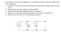
The resistance, inductance and capacitance in a parallel RLC circuit are 1500 ohms, 400mH and
10nF, respectively
a. Calculate the roots of the characteristic equation that describe the voltage response of the
circuit
b. Will the response be over, under or critically damped?
c. What value of C will yield a damped frequency of 15 krad/s?
d. What are the roots of the characteristic equation for the value of C found in (c)?
e. What value of C will result in a critically damped response?

Transcribed Image Text:1. The resistance, inductance and capacitance in a parallel RLC circuit are 1500 ohms, 400mH and
10nF, respectively
a. Calculate the roots of the characteristic equation that describe the voltage response of the
circuit
b. Will the response be over, under or critically damped?
c. What value of C will yield a damped frequency of 15 krad/s?
d. What are the roots of the characteristic equation for the value of C found in (c)?
What value of C will result in a critically damped response?
+
Vo
L
Expert Solution
This question has been solved!
Explore an expertly crafted, step-by-step solution for a thorough understanding of key concepts.
This is a popular solution
Trending nowThis is a popular solution!
Step by stepSolved in 3 steps with 3 images

Knowledge Booster
Learn more about
Need a deep-dive on the concept behind this application? Look no further. Learn more about this topic, electrical-engineering and related others by exploring similar questions and additional content below.Similar questions
- A 39-H inductor is in a series circuit with a 12-V battery and a 25-Qresistor. A switch completing the circuit is closed. When the switch is closed, find the initial voltage difference across the resistor. Answer in Volts.arrow_forwardPRACTICE EXERCISE 4.15 If V = x- y+ xy + 2z V, find E at (1, 2, 3) and the electrostatic energy stored ina cube of side 2 m centered at the origin. Answer: -3a, - 2a, V/m, 0.2358 nJ. 1arrow_forwardUsing the Voltage Divider rule for the circuit shown below, find: Total Impedance The voltage across the Resistor VR The voltage across the Inductor VL The Voltage across the Capacitor VC V1 as shown. Draw all voltages on the Complex Planearrow_forward
- 1arrow_forwardA coil has an equivalent circuit of inductance 1.5 H in series with resistance 90 ohm. It is connected across a charged 5µF capacitor now when the capacitor voltage is 10V. Determine the nature of the response and obtain an expression for the current in the coil.arrow_forwardINCLUDE DIAGRAM FOR UPVOTEarrow_forward
arrow_back_ios
arrow_forward_ios
Recommended textbooks for you
 Introductory Circuit Analysis (13th Edition)Electrical EngineeringISBN:9780133923605Author:Robert L. BoylestadPublisher:PEARSON
 Delmar's Standard Textbook Of ElectricityElectrical EngineeringISBN:9781337900348Author:Stephen L. HermanPublisher:Cengage Learning
 Programmable Logic ControllersElectrical EngineeringISBN:9780073373843Author:Frank D. PetruzellaPublisher:McGraw-Hill Education
 Fundamentals of Electric CircuitsElectrical EngineeringISBN:9780078028229Author:Charles K Alexander, Matthew SadikuPublisher:McGraw-Hill Education
 Electric Circuits. (11th Edition)Electrical EngineeringISBN:9780134746968Author:James W. Nilsson, Susan RiedelPublisher:PEARSON
 Engineering ElectromagneticsElectrical EngineeringISBN:9780078028151Author:Hayt, William H. (william Hart), Jr, BUCK, John A.Publisher:Mcgraw-hill Education,

Introductory Circuit Analysis (13th Edition)
Electrical Engineering
ISBN:9780133923605
Author:Robert L. Boylestad
Publisher:PEARSON

Delmar's Standard Textbook Of Electricity
Electrical Engineering
ISBN:9781337900348
Author:Stephen L. Herman
Publisher:Cengage Learning

Programmable Logic Controllers
Electrical Engineering
ISBN:9780073373843
Author:Frank D. Petruzella
Publisher:McGraw-Hill Education

Fundamentals of Electric Circuits
Electrical Engineering
ISBN:9780078028229
Author:Charles K Alexander, Matthew Sadiku
Publisher:McGraw-Hill Education

Electric Circuits. (11th Edition)
Electrical Engineering
ISBN:9780134746968
Author:James W. Nilsson, Susan Riedel
Publisher:PEARSON

Engineering Electromagnetics
Electrical Engineering
ISBN:9780078028151
Author:Hayt, William H. (william Hart), Jr, BUCK, John A.
Publisher:Mcgraw-hill Education,