Introductory Circuit Analysis (13th Edition)
13th Edition
ISBN: 9780133923605
Author: Robert L. Boylestad
Publisher: PEARSON
expand_more
expand_more
format_list_bulleted
Concept explainers
Question
thumb_up100%
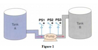
The process shown in figure 1 involves pumping fluid from Tank A to Tank B. The operation of the process can be described as follows,
· Before starting, PS1 must be closed.
· When the start button is pushed, the pump starts. The button can then be released and the pump continues to operate.
· When the stop button is pushed, the pump stops.
· PS2 and PS3 must be closed 8s after the pump starts.
· If either PS2 or PS3 opens, the pump will shutoff and will not be able to start again for another 15 s.
For the above mentioned conditions develop a ladder program using direct method and provide

Transcribed Image Text:PS1 PS2 PS3
Tank
Tank
B
Pump
Figure 1
Expert Solution
This question has been solved!
Explore an expertly crafted, step-by-step solution for a thorough understanding of key concepts.
This is a popular solution
Trending nowThis is a popular solution!
Step by stepSolved in 2 steps with 1 images

Knowledge Booster
Learn more about
Need a deep-dive on the concept behind this application? Look no further. Learn more about this topic, electrical-engineering and related others by exploring similar questions and additional content below.Similar questions
- An electron synchrotron of 6 x 10⁹eV, electrons march through the machine in a roughly circular path 240 meters long. It is normal to have around 1011 electrons circulating in this path during an acceleration cycle. The speed of electrons is practically that of light. What is the current?arrow_forwardThe process diagram of a binary power plant with an ORC-process, utilizing geothermal energy, is presented in figure 1 below. Generator efficiency is 94%, generator output power is 180 kW and evaporator heat power is 2590 kW. Calculate the turbine output power. Round off your answer to one an integer. Heat into process Evaporator Turbine G Feed pump Figure 1. Process diagram of the binary power plant. Generator Condenserarrow_forwardThe diagram representa a primary coil P, carrying a steady current, and a secondary coil S,which is connected to a galvanometer G, The following steps are performed one after another: I. P is pushed rapidly into S II. P is held stationary inside S II, P is withdrawn rapidly from S IV, P is held stationary outside of S During which of these steps does G show a steady zero read Select one: a. II and III only b. II and IV onlyarrow_forward
- In the drilling process shown in Figure 1, there are three cylinders in which cylinders A and B are used to clamp the work piece and Drill cylinder is used to lower and raise the drill. The sequence of operation are as follows: 1. Activate the lever of the 4/2 DCV to start the process 2. Cylinder A and Cylinder B clamps the workpiece at the same time 3. Activate the second DCV (4/2 DCV with spring return) to drill cylinder lowers the drill and raises afterwards (use the throttle valve and check valve to control the speed of the drill low). drill up is normal speed. 4. Once the drill is raised completely, operate the lever to retract cylinder A and cylinder B. Note: provide the following clearly 1. List of the components required 2. Hydraulic circuit with description to each component 3. state diagram should present the sequence of operation sensors Drill-high Drill Drill-Low Part / Material Cylinder A Cylinder B B+ sensors Figure 1: Drilling Process a) Design the Hydraulic Circuit with…arrow_forwardQ. What is the voltage across the load when the push button is depressed ? Q. What would the current flow be if a short-circuit is put accross the battery terminal ?arrow_forwardClick on the tab labeled “Generator.” Make sure “Show Field” is checked; then turn on the water and observe what happens. Consider all the types of energy you’re seeing. Since energy must be conserved, we should be able to account for where it goes at every stage in the process. Explain what happens to the energy, beginning with the water as it leaves the faucet and ending with the light bulb. Your response should include at least five steps and at least five different types of energy.arrow_forward
arrow_back_ios
arrow_forward_ios
Recommended textbooks for you
 Introductory Circuit Analysis (13th Edition)Electrical EngineeringISBN:9780133923605Author:Robert L. BoylestadPublisher:PEARSON
 Delmar's Standard Textbook Of ElectricityElectrical EngineeringISBN:9781337900348Author:Stephen L. HermanPublisher:Cengage Learning
 Programmable Logic ControllersElectrical EngineeringISBN:9780073373843Author:Frank D. PetruzellaPublisher:McGraw-Hill Education
 Fundamentals of Electric CircuitsElectrical EngineeringISBN:9780078028229Author:Charles K Alexander, Matthew SadikuPublisher:McGraw-Hill Education
 Electric Circuits. (11th Edition)Electrical EngineeringISBN:9780134746968Author:James W. Nilsson, Susan RiedelPublisher:PEARSON
 Engineering ElectromagneticsElectrical EngineeringISBN:9780078028151Author:Hayt, William H. (william Hart), Jr, BUCK, John A.Publisher:Mcgraw-hill Education,

Introductory Circuit Analysis (13th Edition)
Electrical Engineering
ISBN:9780133923605
Author:Robert L. Boylestad
Publisher:PEARSON

Delmar's Standard Textbook Of Electricity
Electrical Engineering
ISBN:9781337900348
Author:Stephen L. Herman
Publisher:Cengage Learning

Programmable Logic Controllers
Electrical Engineering
ISBN:9780073373843
Author:Frank D. Petruzella
Publisher:McGraw-Hill Education

Fundamentals of Electric Circuits
Electrical Engineering
ISBN:9780078028229
Author:Charles K Alexander, Matthew Sadiku
Publisher:McGraw-Hill Education

Electric Circuits. (11th Edition)
Electrical Engineering
ISBN:9780134746968
Author:James W. Nilsson, Susan Riedel
Publisher:PEARSON

Engineering Electromagnetics
Electrical Engineering
ISBN:9780078028151
Author:Hayt, William H. (william Hart), Jr, BUCK, John A.
Publisher:Mcgraw-hill Education,