
Introductory Circuit Analysis (13th Edition)
13th Edition
ISBN: 9780133923605
Author: Robert L. Boylestad
Publisher: PEARSON
expand_more
expand_more
format_list_bulleted
Related questions
Question
thumb_up100%
please solve questions 1 to 4 in the calculations section thank you

Transcribed Image Text:The performance and power flow of three phase induction motor
Objective: This test is performed to study the power flow and performance of the three-phase inductionmotor.
Theory: for this test, the three-phase induction motor IM is full loaded (full load test), that's when the inputcurrent of
the loaded three phase IM equals the rated input current given on its name plate. At the end of the full load test,
many parameters which determines the performance of the induction motor is to be calculated.
Experimental Procedure:
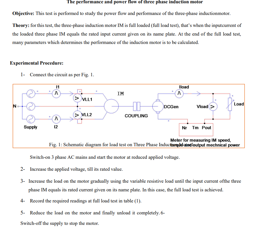
1- Connect the circuit as per Fig. 1.
N
11
A
IM
> VLL1
> VLL2
A
Supply
12
DCGen
COUPLING
Iload
A
Load
Vload >
Nr Tm Pout
Meter for measuring IM speed,
Fig. 1: Schematic diagram for load test on Three Phase Induction que and output mechnical power
Switch-on 3 phase AC mains and start the motor at reduced applied voltage.
2- Increase the applied voltage, till its rated value.
3- Increase the load on the motor gradually using the variable resistive load until the input current ofthe three
phase IM equals its rated current given on its name plate. In this case, the full load test is achieved.
4- Record the required readings at full load test in table (1).
5- Reduce the load on the motor and finally unload it completely. 6-
Switch-off the supply to stop the motor.

Transcribed Image Text:P1
P2
VLL
Nr
Tout
Parameters
(watt)
(watt)
(volt)
(r.p.m)
(mN.m)
Measured
64
77.5
242
1351
654
values
Calculations:
Using tablel, equivalent circuit in figure 1, power flow diagram in figure 2 and the per phase values of
resistances and reactance's of the three phase IM that are calculated in the previous tests, find the following
parameters in the purpose of studying the performance and the power flow of the three phaseinduction motor:
1. Find the synchronous speed Ns, motor slip S and slip speed ns of the three phase IM given that themotor
has four poles fixed at the stator.
2. Find the frequency of the rotor
3. Find the input power factor of the three-phase induction motor
4. Find 11, 10 and 12' using equivalent circuit in Figure 1 (use current divider for 10 and 12').
R1
jX1
R2'
°
jX2'
m
lo
lc
Im
Vph
R2*((1-s)/s)
Rc
jXm
Fig.1. Per phase equivalent circuit diagram of induction motor
5. Find stator copper losses Pstator-Cu
6. Find core losses Pcore
7. Find air gap power Pg
Expert Solution
This question has been solved!
Explore an expertly crafted, step-by-step solution for a thorough understanding of key concepts.

Step by stepSolved in 2 steps with 2 images

Knowledge Booster

Similar questions
- L-1). The 3-phase wound-rotor induction motor has .... . a) high starting torque b) low starting current c) both "a" and "b" d) neither "a" nor "b" L-2). The 3-phase wound-rotor induction.........a) motor has a wire wound rotor b) motor's rotor can be connected to an external resistive load by way of slip rings and brushes c) motor requires more maintenance than the 3-phase squirrel-cage induction motor d) all of the above L-3). The 3-phase wound-rotor induction motor's rotor circuit's resistance should be adjusted so it is__________ during starting. a) low b) high c) either "a" or "b" d) neither "a" nor "b" L-4). Will a 3-phase wound-rotor induction motor start with no external circuit connected to its rotor leads? a) yes b) noarrow_forwardThe starting winding circuit of a capacitor start, induction run motor consists of a 15 Q resistance and a 20 Q2 inductive reactance. These components are in series with a 50 uF capacitor. The circuit is connected to a 120 V, 60 Hz source. Determine: a. the impedance of the series circuit. b. the current. c. the true power. d. the power factor.arrow_forwardDerive the torque equation for a three phase induction motor, with the help of torque speed characteristics curve briefly explain how an induction motor can operate in stable region.arrow_forward
- A 3-phase, 415 V, 50 Hz induction motor draws 5 times the rated current at rated voltage at starting. It is required to bring down the starting current from the supply to 2 times of the rated current using a 3-phase autotransformer. If the magnetizing impedance of the induction motor and no load current of the autotransformer is neglected, then the transformation ratio of the autotransformer is given by. (round off to two decimal places).arrow_forwardThree Phase Induction Mot... The relative speed of stator magnetic field with respect to rotor of a 30 induction motor with 4 pole, 50 Hz frequency. If the slip is 0.05.arrow_forwardThe stator resistance of a 1-phase induction motor is 2.5 ohms and its leakage reactance is 2.0 ohms. Onno-load, the motor takes 4 A at 96 V and at 0.25 lagging power factor. The no-load friction andwindage loss is negligible. Under the blocked-rotor condition, the input power is 130 W at 6 A and42 V. Obtain the equivalent circuit parameters.arrow_forward
- Question A 3-phase, 415 V, 4-pole, 50 Hz induction motor draws 5 times the rated current at rated voltage at starting. It is required to bring down the starting current from the supply to 2 times of the rated current using a 3-phase autotransformer. If the magnetizing impedance of the induction motor and no-load current of the autotransformer is neglected, then the transformation ratio of the autotransformer is given byarrow_forwardFind the value:arrow_forwardMotor efficiency is ............... % ? Air gap power is .............. W ? Percentage slip is equal to ...........% ? Rotor copper loss is ............ W ?arrow_forward
arrow_back_ios
arrow_forward_ios
Recommended textbooks for you
- Introductory Circuit Analysis (13th Edition)Electrical EngineeringISBN:9780133923605Author:Robert L. BoylestadPublisher:PEARSON
 Delmar's Standard Textbook Of ElectricityElectrical EngineeringISBN:9781337900348Author:Stephen L. HermanPublisher:Cengage Learning
 Programmable Logic ControllersElectrical EngineeringISBN:9780073373843Author:Frank D. PetruzellaPublisher:McGraw-Hill Education
  Fundamentals of Electric CircuitsElectrical EngineeringISBN:9780078028229Author:Charles K Alexander, Matthew SadikuPublisher:McGraw-Hill Education
 Electric Circuits. (11th Edition)Electrical EngineeringISBN:9780134746968Author:James W. Nilsson, Susan RiedelPublisher:PEARSON
 Engineering ElectromagneticsElectrical EngineeringISBN:9780078028151Author:Hayt, William H. (william Hart), Jr, BUCK, John A.Publisher:Mcgraw-hill Education,
Introductory Circuit Analysis (13th Edition)
Electrical Engineering
ISBN:9780133923605
Author:Robert L. Boylestad
Publisher:PEARSON
Delmar's Standard Textbook Of Electricity
Electrical Engineering
ISBN:9781337900348
Author:Stephen L. Herman
Publisher:Cengage Learning
Programmable Logic Controllers
Electrical Engineering
ISBN:9780073373843
Author:Frank D. Petruzella
Publisher:McGraw-Hill Education
Fundamentals of Electric Circuits
Electrical Engineering
ISBN:9780078028229
Author:Charles K Alexander, Matthew Sadiku
Publisher:McGraw-Hill Education
Electric Circuits. (11th Edition)
Electrical Engineering
ISBN:9780134746968
Author:James W. Nilsson, Susan Riedel
Publisher:PEARSON
Engineering Electromagnetics
Electrical Engineering
ISBN:9780078028151
Author:Hayt, William H. (william Hart), Jr, BUCK, John A.
Publisher:Mcgraw-hill Education,