
Power System Analysis and Design (MindTap Course List)
6th Edition
ISBN: 9781305632134
Author: J. Duncan Glover, Thomas Overbye, Mulukutla S. Sarma
Publisher: Cengage Learning
expand_more
expand_more
format_list_bulleted
Question
thumb_up100%
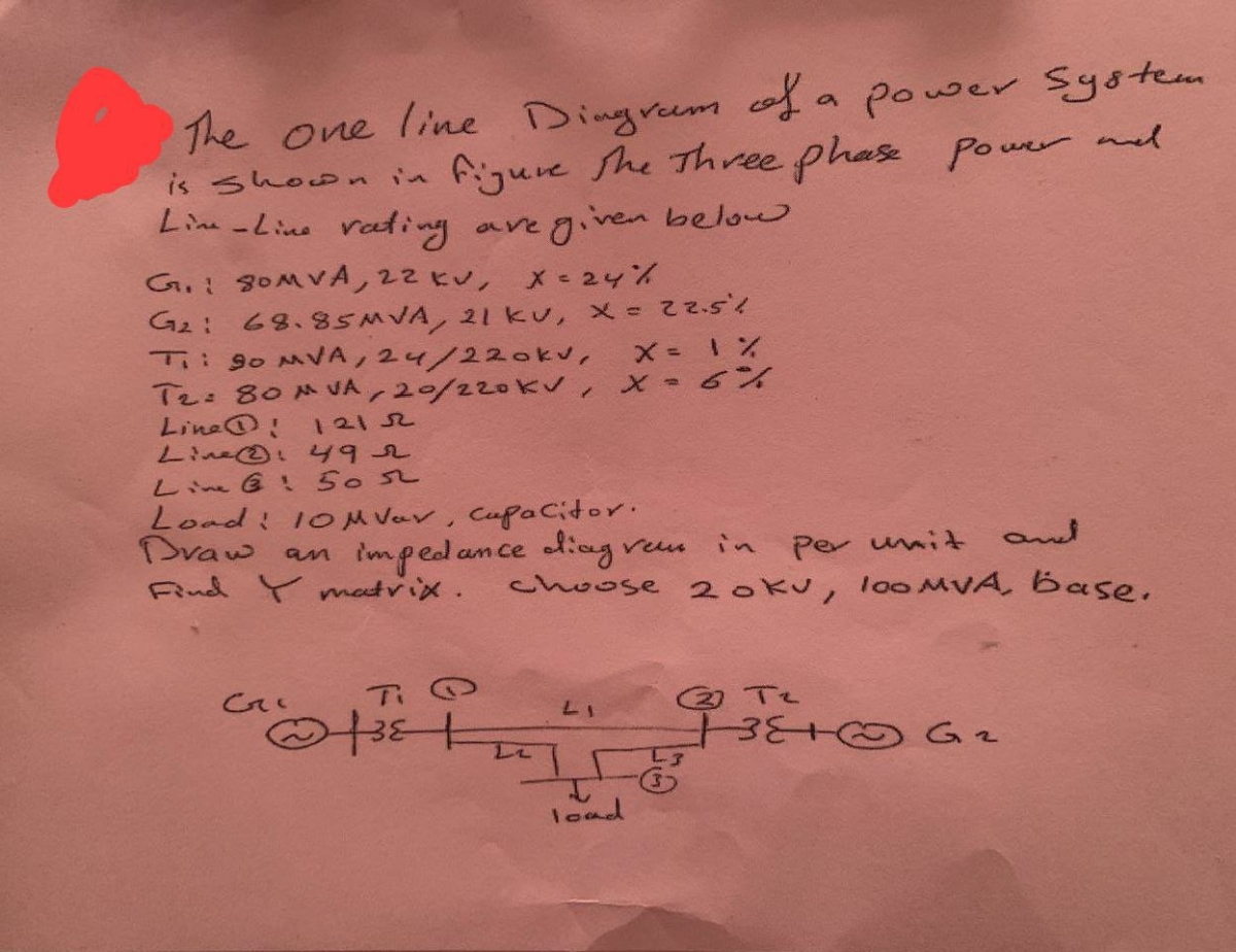

Transcribed Image Text:The one line Diagram of a power system
is shown in figure the Three phase power and
Line-Line rating are given below
G. 80MVA, 22 kV, X = 24%
G2: 68.85MVA, 21 kv, x = 22.5%.
T: 90 MVA, 24/220kv,
X = 1%
T2: 80 M VA, 20/220 kV, x=6%
Line!
121 J
Line: 49 r
Line ! 50 π
Load: 10M var, Capacitor.
Draw an
impedance diag veu
in
Per unit and
Find matrix.
choose 2 oku, loo MVA, base.
Tz
G
0438
LI
LET G2
T
load
Expert Solution
This question has been solved!
Explore an expertly crafted, step-by-step solution for a thorough understanding of key concepts.

Step by stepSolved in 2 steps with 5 images

Knowledge Booster

Similar questions
- Q4/For the three-phase power network shown in Figure. the various components are: GI: 100 MVA, 0.30 pu reactance. G2: 60 MVA, 0.18 pu reactance. Transformers (cach): 50 MVA, 0.10 pu reactance. Inductive reactor X: 0.20 pu on a base of 100 MVA. Lines (each): 80 ohms (reactive); neglect resistance. with the network initially unloaded and a line voltage of 110 kV, a symmetrical short circuit occurs at midpoint E of line 2. Calculate the short circuit MVA to be interrupted by the circuit breakers A and B at the ends of the line. T3 38 L1 L2 G2 Bas 12 T4 Busarrow_forward3. The single-line diagram of a three-phase power system is as shown in Figure Al-3. Impedances are marked in per unit on a 100-MVA, 400-kV base. The load at bus 2 is S2 = 15.93 MW – j 33.4 Mvar, and at bus 3 is S3 = 77 MW +jl4 Mvar. It is required to hold the voltage at bus 3 at 40020° kV. Working in per unit, determine the voltage at buses 2 and 1. V2 V1 V3 j0.5 pu j0.4 pu S2 S3 Figure A1-3arrow_forward2. The one-line diagram of a three-phase power system is as shown in the figure below. Impedances are marked in per unit on a 100-MVA, 400-kV base. The load at bus 2 is S2 = 15.93 MW-j33.4 Mvar, and at bus 3 is S3 = 77 MW +j14 Mvar. It is required to hold the voltage at bus 3 at 4006 0 kV. Working in per unit, determine the voltage at buses 2 and 1. V3 j0.5 pu V₂ S₂ j0.4 pu S3arrow_forward
- Q1 Figure 1 shows the online diagram of a three-phase power system. By selecting a common base of 100 MVA and 22 kV on the generator side, draw an impedance diagram showing all impedancesincluding the load impedance in per-unit. The data are given as follows: G: 100 MVA 22 kV x= 0.18 per unitT1: 60 MVA 22/220 kVT2: 40 MVA 220/11 kVT3: 40 MVA 22/110 kVT4: 40 MVA 110/11 kVM: 66.5 MVA 10.45 kVLines 1 and 2 have series reactance’s of 48.4 and 65.43 V, respectively. Atbus 4, the three-phase load absorbs 57 MVA at 10.45 kV and 0.6 power factor lagging.Figure 1x =0.10 per unit x = 0.06 per unitx =0.064 per unit x= 0.08 per unit x =0.185 per unitarrow_forwardPlease solve all steps in detail to understandarrow_forwardHigh voltage engineering subjectarrow_forward
- Draw an impedance diagram for the electric power system shown in Figure 3.32 showing all impedances in per unit on a 100-MVA base. Choose 20-kV as the voltage base for generator. The three-phase power and line-line ratings are given below. G1; 90 MVA 20 kV T1: 80 MVA T2: 80 MVA 90 MVA G2: Line: Load: G₁ T₁ 38 1 20/200 kV 200/20 kV 18 kV 200 kV 200 kV Load FIGURE 3.32 One-line diagram for Problem 3.13 Line X = 9% X = 16% X = 20% X = 9% X = 120 Ω S = 48 MW + j64 Mvar T₂ 38 2 G₂arrow_forwardQ2) A 13.2-kV single-phase generator supplies power to a load through a transmission line. The load's impedance is Zload = 500 236.87° ohm, and the transmission line's impedance is Zline = 60 253.1° ohm. To reduce transmission line losses to 0.0103 of its losses without using the transformers design and use two transformers T1 between the generator and the transmission line and T2 between the transmission line and the load.arrow_forwardFigure below shows the one line diagram of a 3-o system. By selecting a common base of 100 MVA and 22 KV on the generator side, draw an impedance diagram showing all impedances including the load impedance in per unit. The data are given as follows: G: 100 MVA, 22 KV, X= 0.18 pu 22/220 KV, X= 0.1 pu TR1: 50 MVA, TR2: 40 MVA, 220/11 KV, X=0.06 pu Load 1: 50 MVA, 0.8 pf lag Load 2: 50 MVA, 0.8 pf lead If volt at bus 4 equal 11 KV constant value : calculate i) volt at bus 1 ii) EMF (Eg) of generator ii) Transmission line current TR1 TR2 ZTL=j80 2 G1 3. 4 Load 1 Load 2arrow_forward
- The one-line diagram of a three-phase power system is as shown in the figure attached. Impedances are marked in per unit on a 100-MVA, 400-kv base. The load at bus 2 is S(sub 2) = 15.93 MW - j33.4 Mvar, and bus 3 is S(sub 3) = 77MW + j14 Mvar. I tis required to hold the voltage at bus 3 at 400 angle 0 degrees kV. Working in per unit, determine the voltage at buses 2 and 1.arrow_forwardPlz sir solve this and explain each step properlyarrow_forwardRefer to the given answer so that i will know how.arrow_forward
arrow_back_ios
SEE MORE QUESTIONS
arrow_forward_ios
Recommended textbooks for you
- Power System Analysis and Design (MindTap Course ...Electrical EngineeringISBN:9781305632134Author:J. Duncan Glover, Thomas Overbye, Mulukutla S. SarmaPublisher:Cengage Learning
Power System Analysis and Design (MindTap Course ...
Electrical Engineering
ISBN:9781305632134
Author:J. Duncan Glover, Thomas Overbye, Mulukutla S. Sarma
Publisher:Cengage Learning