Introductory Circuit Analysis (13th Edition)
13th Edition
ISBN: 9780133923605
Author: Robert L. Boylestad
Publisher: PEARSON
expand_more
expand_more
format_list_bulleted
Concept explainers
Question

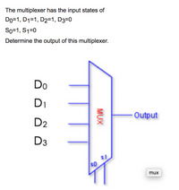
Transcribed Image Text:The multiplexer has the input states of
Do=1, D1=1, D2=1, D3=0
So=1, S1=0
Determine the output of this multiplexer.
Do
Di
Output
D2
D3
s0
mux
MUX
Expert Solution
This question has been solved!
Explore an expertly crafted, step-by-step solution for a thorough understanding of key concepts.
This is a popular solution
Trending nowThis is a popular solution!
Step by stepSolved in 2 steps with 1 images

Knowledge Booster
Learn more about
Need a deep-dive on the concept behind this application? Look no further. Learn more about this topic, electrical-engineering and related others by exploring similar questions and additional content below.Similar questions
- please answer all thanks !arrow_forward1. The input signal in Figure 1(a) is applied to the comparator in Figure 1(b).Draw the output showing its proper relationship to the input signal. Assume the maximum output levels of the comparator are (+/-)12 V. Values of R1 and R2 are as follows. (a)R1 = 7 K Ohm, R2 = 3 K Ohm (b)R1 = 3 K Ohm, R2 = 7 K Ohm Handwriting +10 Volt R1 Vin 0 oVout Vin R2 -5 V Figure 1(b) Figure 1(a)arrow_forwardListen A 12 bit DAC has a lower reference voltage of OV and an upper reference voltage of 3.0V What is the output voltage for a code of Ox74B? Round the answer to 2 decimal places. a) 1.37V Ob) 1.50V c) 1.60V O d) 1.12Varrow_forward
- SOLVE STEP BY STEP IN DIGITAL FORMAT For each of the circuits shown below, draw its voltage transfer curve, using the constant-drop model (all diodes are silicon identical, V_Don = 0.7V). Consider a variation of the input voltage from -10V to +10V. Vi D₁ A D2₂ 1k Circuit 2 + Vo 오 Vi à D₁ 1k www 1k Circuit 4 + V₂arrow_forwardWhat is the output (in decimal format) of a 10-bit unipolar A/D converter for the input of 100mV? Assume that the converter uses 5V as a reference voltage for conversion purposes. The converter input range is 0V to 5V. Round your answer to the nearest integer value.arrow_forwardWhat are 8 degenerate 2 level forms in digital electronics? How can 2 level forms be used to extend the number of inputs to gate?arrow_forward
- Please in typing format please ASAP for Thanks ?arrow_forwardfind the average power consume by RL for both fullwave and halfwave rectifier circuit.arrow_forwardIn the circuit shown below, if VA= 1V and V-2V, the statuses of the diodes are (Assuming ideal diodes) D₁ VA V₂₁ D₂ ERL Vout Select one: O a D₂ is ON, D₂ is ON O b. None of these Oc. Dy is OFF, D₂ is ON O d. Dy is ON, D₂ is OFFarrow_forward
- Quèstion 15 Power supply circuit is delivering 0.5 A and an average voltage 20 V to the load as shown in the circuit below. The ripple voltage of the half wave rectifier is 0.5 V and the diode is represented using constant voltage model. The smoothing capacitor value is equal to IL-DE 205A iL-DC 220V ams 5OH23 VL-DC =20V 0.01 F 0.02 F 0.0167 F None of the above SHOT ON RED MAGIC 5S POWERED BY NUBIAarrow_forwardThe data-input and data-select waveforms in Figure 7 are applied to the multiplexer. Determine the output waveform F in relation to the inputs.arrow_forwardC'uk Converter Design A C'uk converter has an input of 12 V and is to have an output of - 24 V supplying a 60 W load. Select the duty ratio, the switching frequency, the inductor sizes such that the change in inductor currents is no more than 12 percent of the average inductor current, the output ripple voltage is no more than 1.5 percent, and the ripple voltage across C1 is no more than 3 percent.arrow_forward
arrow_back_ios
arrow_forward_ios
Recommended textbooks for you
 Introductory Circuit Analysis (13th Edition)Electrical EngineeringISBN:9780133923605Author:Robert L. BoylestadPublisher:PEARSON
 Delmar's Standard Textbook Of ElectricityElectrical EngineeringISBN:9781337900348Author:Stephen L. HermanPublisher:Cengage Learning
 Programmable Logic ControllersElectrical EngineeringISBN:9780073373843Author:Frank D. PetruzellaPublisher:McGraw-Hill Education
 Fundamentals of Electric CircuitsElectrical EngineeringISBN:9780078028229Author:Charles K Alexander, Matthew SadikuPublisher:McGraw-Hill Education
 Electric Circuits. (11th Edition)Electrical EngineeringISBN:9780134746968Author:James W. Nilsson, Susan RiedelPublisher:PEARSON
 Engineering ElectromagneticsElectrical EngineeringISBN:9780078028151Author:Hayt, William H. (william Hart), Jr, BUCK, John A.Publisher:Mcgraw-hill Education,

Introductory Circuit Analysis (13th Edition)
Electrical Engineering
ISBN:9780133923605
Author:Robert L. Boylestad
Publisher:PEARSON

Delmar's Standard Textbook Of Electricity
Electrical Engineering
ISBN:9781337900348
Author:Stephen L. Herman
Publisher:Cengage Learning

Programmable Logic Controllers
Electrical Engineering
ISBN:9780073373843
Author:Frank D. Petruzella
Publisher:McGraw-Hill Education

Fundamentals of Electric Circuits
Electrical Engineering
ISBN:9780078028229
Author:Charles K Alexander, Matthew Sadiku
Publisher:McGraw-Hill Education

Electric Circuits. (11th Edition)
Electrical Engineering
ISBN:9780134746968
Author:James W. Nilsson, Susan Riedel
Publisher:PEARSON

Engineering Electromagnetics
Electrical Engineering
ISBN:9780078028151
Author:Hayt, William H. (william Hart), Jr, BUCK, John A.
Publisher:Mcgraw-hill Education,