
Structural Analysis
6th Edition
ISBN: 9781337630931
Author: KASSIMALI, Aslam.
Publisher: Cengage,
expand_more
expand_more
format_list_bulleted
Related questions
Concept explainers
Question

Transcribed Image Text:**Problem Statement:**
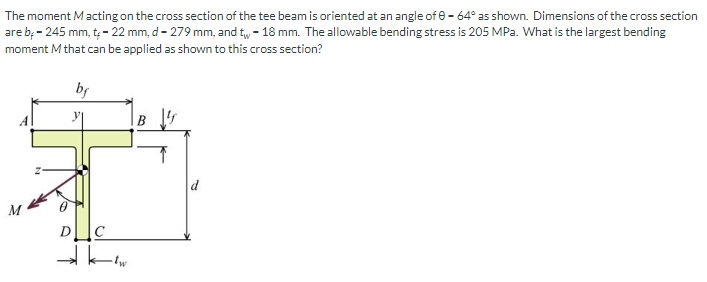
The moment \( M \) acting on the cross section of the tee beam is oriented at an angle of \( \theta = 64^\circ \) as shown. Dimensions of the cross section are \( b_f = 245 \text{ mm}, t_f = 22 \text{ mm}, d = 279 \text{ mm}, \) and \( t_w = 18 \text{ mm}. \) The allowable bending stress is 205 MPa. What is the largest bending moment \( M \) that can be applied as shown to this cross section?
**Diagram Explanation:**
The diagram illustrates a tee beam cross section with labeled dimensions:
- \( b_f \) is the width of the flange.
- \( t_f \) is the thickness of the flange.
- \( d \) is the overall depth of the beam.
- \( t_w \) is the thickness of the web.
Points A, B, C, and D define corners of the tee shape, and the centroid is marked at point \( z \). The moment \( M \) acts at an angle \( \theta \) from the vertical axis of the cross section.
![Certainly! Here’s a transcription suitable for an educational website:
---
### Part 2
**Problem Statement:**
The z-component of moment M will cause compression at points A and B, and tension at points C and D. Conversely, the y-component of moment M will cause compression at points A and D, and tension at points B and C. The maximum tensile bending stress is expected to occur at point C. Your task is to determine the magnitude of the largest bending moment that can be applied such that the stress at corner C does not exceed 205 MPa.
**Answer:**
M = \( \boxed{8.31 \times 10^1} \) kN-m
**Feedback:**
- Status: Incorrect answer.
*Additional Resources:*
- eTextbook and Media
[Submit Answer]
---
### Part 3
**Problem Statement:**
The z-component of moment M will cause compression at points A and B, and tension at points C and D. The y-component of moment M will cause compression at points A and D, and tension at points B and C. The maximum compressive bending stress will occur at point A. Determine the magnitude of the largest bending moment that can be applied so that the stress at corner A does not exceed 205 MPa.
**Answer:**
M = \( \boxed{} \) kN-m
*Attempts: 0 of 5 used*
[Submit Answer]
*Additional Resources:*
- eTextbook and Media
[Save for Later]
---
### Part 4
**Problem Statement:**
Determine the maximum bending moment that can be applied to this cross-section.
**Feedback:**
- Status: Incorrect answer.
---
In this scenario, you're tasked with calculating the largest permissible bending moment based on stress constraints at specific corners of a beam or structural member, taking into account compression and tension influences from moment components.](https://content.bartleby.com/qna-images/question/99e37c92-095a-4cae-adf6-01aeaaa5668c/adb5781d-4b74-4852-875b-652618e22612/vc9ay3k_processed.png)
Transcribed Image Text:Certainly! Here’s a transcription suitable for an educational website:
---
### Part 2
**Problem Statement:**
The z-component of moment M will cause compression at points A and B, and tension at points C and D. Conversely, the y-component of moment M will cause compression at points A and D, and tension at points B and C. The maximum tensile bending stress is expected to occur at point C. Your task is to determine the magnitude of the largest bending moment that can be applied such that the stress at corner C does not exceed 205 MPa.
**Answer:**
M = \( \boxed{8.31 \times 10^1} \) kN-m
**Feedback:**
- Status: Incorrect answer.
*Additional Resources:*
- eTextbook and Media
[Submit Answer]
---
### Part 3
**Problem Statement:**
The z-component of moment M will cause compression at points A and B, and tension at points C and D. The y-component of moment M will cause compression at points A and D, and tension at points B and C. The maximum compressive bending stress will occur at point A. Determine the magnitude of the largest bending moment that can be applied so that the stress at corner A does not exceed 205 MPa.
**Answer:**
M = \( \boxed{} \) kN-m
*Attempts: 0 of 5 used*
[Submit Answer]
*Additional Resources:*
- eTextbook and Media
[Save for Later]
---
### Part 4
**Problem Statement:**
Determine the maximum bending moment that can be applied to this cross-section.
**Feedback:**
- Status: Incorrect answer.
---
In this scenario, you're tasked with calculating the largest permissible bending moment based on stress constraints at specific corners of a beam or structural member, taking into account compression and tension influences from moment components.
Expert Solution
This question has been solved!
Explore an expertly crafted, step-by-step solution for a thorough understanding of key concepts.

This is a popular solution

Trending nowThis is a popular solution!

Step by stepSolved in 4 steps with 12 images

Knowledge Booster


Learn more about
Need a deep-dive on the concept behind this application? Look no further. Learn more about this topic, civil-engineering and related others by exploring similar questions and additional content below.Similar questions
- Part 2,3,4arrow_forwardTwo wooden studs with cross-sectional dimensions 45×145 mm2 are glued together to form a beam with a T-sectionaccording to the figure on the right and loaded according to the figure on the left. The beam is loaded in its rigiddirection.a) Calculate the moment of inertia of the cross-section about the centroid axis (z-axis).b) Calculate the maximum normal stress in the beam.c) Sketch the normal stress distribution over the most loaded cross-section of the beam. All calculations must be clear and handwritten, draw and check so that the answers are correctarrow_forward.arrow_forward
- If the force in member C is -4.3 kip, what is the force in member D? A Type your answer...arrow_forwardCould you please provide a conceptual explanation with this?arrow_forwardA steel pipe is subjected to the 16-kN load shown below. Its outside diameter is 140 mm and its thickness is 7 mm. Consider that the yield strength of steel is 240 MPa. Analyze point H ONLY. Due to the pressure in the pipe, there is an 11.25-MPa (T) normal stress along x and a 22.50-MPa (T) normal stress along z of point H. A. Determine the internal forces and moments at the pertinent section through an FBD. B. Determine the stresses experienced by point H. Illustrate using a stress element. C. Determine the FS by MSST at point H D. Determine the von Mises equivalent stress at point H E. Determine the FS by MDET at point H 700 mm 16 KN 1,300 mmarrow_forward
- Problem 2 The rigid bar is plnned at A and held by two flexible bars at E and C. The load P Is applled at B. The two flexible bars FE and DC each have a diameter of 1 In. The flexible bars are elastic- perfectly plastic with a yleld stress equal to 20 ksl and a yleld strain of 0.001. Determine the following: The load R, at first yleld and the corresponding deflection at B, &, The ultimate load Pu and the corresponding deflection du The permanent deflection and residual stresses in each rod if the ultimate load is removed Construct P - A curve showing yield, ultimate and permanent deformation o (ksi) 1 ft E F 1 ft1 ft 20 B P e (in./in.) 0.001 1 ft D 2 ft 1 ft Aarrow_forward5 - An aluminum circular shaft, fixed at both ends, is loaded by torques applied at points B and C, as shown in the figure. The bar material has a shear modulus G = 85 GPa. Plot the maximum shear stress and angle of twist along the length of the shaft. A D TB 0.5m Tc 0.9m с 0.4m 40mm ↑ TB-10KN-m Tc=15KN.marrow_forwardA cross-section is subjected to a maximum shear of V=160 kN (see figure): Determine the centroid of the cross-section. Calculate the moment of inertia (I) of the cross-section. Determine the shear stress at point A in the cross-section.arrow_forward
arrow_back_ios
arrow_forward_ios
Recommended textbooks for you
 Structural Analysis (10th Edition)Civil EngineeringISBN:9780134610672Author:Russell C. HibbelerPublisher:PEARSON
 Principles of Foundation Engineering (MindTap Cou...Civil EngineeringISBN:9781337705028Author:Braja M. Das, Nagaratnam SivakuganPublisher:Cengage Learning
 Fundamentals of Structural AnalysisCivil EngineeringISBN:9780073398006Author:Kenneth M. Leet Emeritus, Chia-Ming Uang, Joel LanningPublisher:McGraw-Hill Education
 Traffic and Highway EngineeringCivil EngineeringISBN:9781305156241Author:Garber, Nicholas J.Publisher:Cengage Learning
Structural Analysis (10th Edition)
Civil Engineering
ISBN:9780134610672
Author:Russell C. Hibbeler
Publisher:PEARSON
Principles of Foundation Engineering (MindTap Cou...
Civil Engineering
ISBN:9781337705028
Author:Braja M. Das, Nagaratnam Sivakugan
Publisher:Cengage Learning
Fundamentals of Structural Analysis
Civil Engineering
ISBN:9780073398006
Author:Kenneth M. Leet Emeritus, Chia-Ming Uang, Joel Lanning
Publisher:McGraw-Hill Education
Traffic and Highway Engineering
Civil Engineering
ISBN:9781305156241
Author:Garber, Nicholas J.
Publisher:Cengage Learning