
College Physics
11th Edition
ISBN: 9781305952300
Author: Raymond A. Serway, Chris Vuille
Publisher: Cengage Learning
expand_more
expand_more
format_list_bulleted
Related questions
Concept explainers
Question
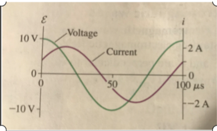
The graph below represents the voltage and current of a series RLC circuit.
a) Find R
b) Find the resonance frequency if L = 200 µH

Transcribed Image Text:**Understanding Voltage and Current Waveforms**
The provided image displays a graph with two sinusoidal waveforms, representing voltage (denoted as \( E \)) and current (denoted as \( i \)) over time.
### Graph and Axes Explanation:
- **Horizontal Axis (Time Axis):**
- Denoted in microseconds (µs), the time axis spans from 0 to 100 µs, marked at intervals of 50 µs.
- **Vertical Axes:**
- **Left Vertical Axis (Voltage):**
- Denoted in volts (V), it ranges from -10 V to 10 V.
- **Right Vertical Axis (Current):**
- Denoted in amperes (A), it ranges from -2 A to 2 A.
### Voltage and Current Waveforms:
- **Voltage Waveform (Purple Curve):**
- The voltage waveform is a sinusoidal curve originating at 0 V at \( t = 0 \) µs.
- It peaks at 10 V at approximately 25 µs and -10 V at around 75 µs, then returns to 0 V at 100 µs.
- **Current Waveform (Green Curve):**
- The current waveform, similarly sinusoidal, also starts at 0 A at \( t = 0 \) µs.
- It peaks at 2 A at around 50 µs and -2 A at about 100 µs, similarly returning to 0 A at 100 µs.
### Observations:
- **Phase Difference:**
- It can be observed that there is a phase difference between the voltage and current waveforms. The voltage peaks and zero crossings are not aligned exactly with those of the current. The current appears to lag behind the voltage.
### Educational Value:
Such graphs are critical in understanding AC (alternating current) circuits where voltage and current vary sinusoidally over time. The phase difference between the voltage and current is crucial in analyzing the power factor and energy flow in the circuit.
**Conclusion:**
The graph helps visualize the relationship between current and voltage in AC circuits, highlighting the phase difference and how the sinusoidal variations interact over time.
Expert Solution
This question has been solved!
Explore an expertly crafted, step-by-step solution for a thorough understanding of key concepts.

Step by stepSolved in 2 steps with 3 images

Knowledge Booster


Learn more about
Need a deep-dive on the concept behind this application? Look no further. Learn more about this topic, physics and related others by exploring similar questions and additional content below.Similar questions
- The resonance frequency of a series RLC circuit is 5500 Hz What is the resonance frequency if the inductance L is doubled? Express your answer with the appropriate units. fo = 3900 Hz Submit Previous Answers v Correct Part C What is the resonance frequency if the capacitance C is doubled? Express your answer with the appropriate units. HA ? fo = Value Units Submit Request Answerarrow_forwardConsider the RLC series circuit shown in the figure below where R = 420Ω, L = 75 mH, and C = 0.750 µF. The current in the circuit is given byi(t) = I cos[(9050 rad/s)t], where I is the amplitude current. Find the phaseshift between the source voltage relative to the current in the circuit.arrow_forward(a) A series RLC circuit is shown in the figure below. (170 V) sin 120 mt 5.0 Ω A Series RLC Circuit. 0000 25 mH Calculate the linear freq ency (in Hz) of the voltage source. Hz Calculate the resonance frequency. Hz Calculate the impedance at resonance. 2 400 μF Calculate the current at resonance. Aarrow_forward
- Group Work Certain heavy industrial equipment uses AC power that has a peak voltage of 679 V. What is the rms voltage? A certain circuit breaker trips when the rms current is 15.0 A. What is the corresponding peak current?arrow_forwardAn RLC circuit is driven by an AC generator of frequency w. The generator voltage can be represented by Et) - Emax cos(ur) and the current by t) - max cos(wr-p). The peak generator voltage Emax, the peak current /max- and the phase angle p by which the generator EMF leads the current are given in the figure. R E- 20 V Ina = 2.3 A = +30 The average power dissipated by the resistor is:arrow_forwardPlease give a detailed solutionarrow_forward
arrow_back_ios
arrow_forward_ios
Recommended textbooks for you
- College PhysicsPhysicsISBN:9781305952300Author:Raymond A. Serway, Chris VuillePublisher:Cengage Learning
 University Physics (14th Edition)PhysicsISBN:9780133969290Author:Hugh D. Young, Roger A. FreedmanPublisher:PEARSON
 Introduction To Quantum MechanicsPhysicsISBN:9781107189638Author:Griffiths, David J., Schroeter, Darrell F.Publisher:Cambridge University Press
  Physics for Scientists and EngineersPhysicsISBN:9781337553278Author:Raymond A. Serway, John W. JewettPublisher:Cengage Learning
 Lecture- Tutorials for Introductory AstronomyPhysicsISBN:9780321820464Author:Edward E. Prather, Tim P. Slater, Jeff P. Adams, Gina BrissendenPublisher:Addison-Wesley
 College Physics: A Strategic Approach (4th Editio...PhysicsISBN:9780134609034Author:Randall D. Knight (Professor Emeritus), Brian Jones, Stuart FieldPublisher:PEARSON
College Physics
Physics
ISBN:9781305952300
Author:Raymond A. Serway, Chris Vuille
Publisher:Cengage Learning
University Physics (14th Edition)
Physics
ISBN:9780133969290
Author:Hugh D. Young, Roger A. Freedman
Publisher:PEARSON
Introduction To Quantum Mechanics
Physics
ISBN:9781107189638
Author:Griffiths, David J., Schroeter, Darrell F.
Publisher:Cambridge University Press
Physics for Scientists and Engineers
Physics
ISBN:9781337553278
Author:Raymond A. Serway, John W. Jewett
Publisher:Cengage Learning
Lecture- Tutorials for Introductory Astronomy
Physics
ISBN:9780321820464
Author:Edward E. Prather, Tim P. Slater, Jeff P. Adams, Gina Brissenden
Publisher:Addison-Wesley
College Physics: A Strategic Approach (4th Editio...
Physics
ISBN:9780134609034
Author:Randall D. Knight (Professor Emeritus), Brian Jones, Stuart Field
Publisher:PEARSON