Concept explainers
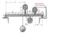
The frame shown supports a load W DE 1000 lb through the cable that passes through 3 pulleys and at the end is attached to a frame, also supports the distributed loads ω1 = 100 lb / ft; ω2 = 60 lb / ft and ω3 = 50 lb / ft. Determine:
1. Reactions at supports A and E.
2. Forces acting on bar ABCDE, show the results in graphical form of the beam. That is, you must make the simplified free-body diagram of the loads that act only on the horizontal element.
3. Make the shear force and bending-moment diagrams for the entire beam. The geometry and load data are as follows:
see the geometry and load in the images.
Clarification: THE CABLE GOES BEHIND THE FRAME AND THE CONTACT IS ONLY WITH THE PULLEYS AND THE GRIP TO THE FRAME (WALL).
All pulleys have the same radius.


Trending nowThis is a popular solution!
Step by stepSolved in 5 steps with 5 images

- 1.Calculare the Magnitude (absolute value) of the force in member CA in newtons.The correct answer is 178.9N 2.Calculate the Magnitude(absolute value) of the reaction force vertical component at the pin connection B in Newton metres.The correct answer is 166.3Narrow_forward4. Solve parts (b) and (c). Calculate also the pin reactions at C. Remember to show the direction of all resulting forces by arrows. Draw all necessary FBDS, and clearly show which FBD you consider for each equilibrium equation. When showing your resulting internal reactions at pins, mention the member on which they act. The 48-lb load can be moved along the line of action shown and applied at A, D, or E. Determine the components of the reactions at B and F if the 48-lb load is applied (a) at A, (b) at D, (c) at E. 48 lb 5 in. ID 7 in. LE F.arrow_forwardDo not forget to box your final answer.arrow_forward
- Please solve the following probem step by step. Solve eveything!arrow_forwardIn this part, you should base your calculations upon a material of your choice. You have to assume areasonable factor of safety.B.1 Determine the maximum force P that can be supported at joint D .B.2 calculate the cross-sectional area of each member to safely carry the axial load.arrow_forwardI need help with this exercise from my homework. I have no idea about how to solve it. I need an step by step solving and explanation, please.arrow_forward
- Cantilever beam AD is supported at A. A crossbar 2 m in length is welded at its center to the beam at C. Lengths AB, BC, and CD each are 2 m long. Find: (1) FAX, the x-component of FA, the resultant force at A (2) FAy, the y-component of FA (3) MAmag, the magnitude of the resultant couple moment at A Express your answers as Newtons and Newton-meters. F1 a1 2 m 2m F2 1m 1 m V Answer all numeric solutions with five significant figures. F1 = 28.2 N a1 = 64.1 deg a2 F2 a2 2 m F2 = 32.5 N a1 F1 a2 = 33.9 degarrow_forwardDetermine the magnitude of the pin force at A. Assume W = 800 lb, a = 4.3 ft, b = 3.2 ft, r= 8 in. B W D Answer: A = i Ibarrow_forwardDetermine the maximum moment in kip-ft for the beams shown below using th method of consistent deformations. Select the reaction at the interior support to b the redundant. Express your answer in absolute value and use two decimal places 3 k/ft -B 25 ft 15 ft 21 E = 29,000 ksi I= 2,500 in.+arrow_forward

 Structural Analysis (10th Edition)Civil EngineeringISBN:9780134610672Author:Russell C. HibbelerPublisher:PEARSON
 Principles of Foundation Engineering (MindTap Cou...Civil EngineeringISBN:9781337705028Author:Braja M. Das, Nagaratnam SivakuganPublisher:Cengage Learning
 Fundamentals of Structural AnalysisCivil EngineeringISBN:9780073398006Author:Kenneth M. Leet Emeritus, Chia-Ming Uang, Joel LanningPublisher:McGraw-Hill Education
 Traffic and Highway EngineeringCivil EngineeringISBN:9781305156241Author:Garber, Nicholas J.Publisher:Cengage Learning


