Introductory Circuit Analysis (13th Edition)
13th Edition
ISBN: 9780133923605
Author: Robert L. Boylestad
Publisher: PEARSON
expand_more
expand_more
format_list_bulleted
Question
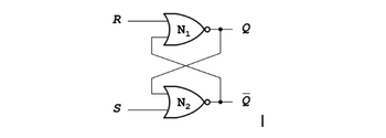
The following figure shows SR latch that is the most fundamental building block using static gates. Answer the following questions.
(Note: You should show all the steps)
1. What are the outputs Q and Q when both inputs S and R are FALSE (or “0”)?
2. Fill out the truth table of SR Latch.

Transcribed Image Text:The diagram illustrates an S-R Latch, which is a fundamental memory element in digital electronics. It consists of two cross-coupled NOR gates, labeled as \(N_1\) and \(N_2\).
### Components and Connections:
- **Inputs:**
- \(R\): The reset input.
- \(S\): The set input.
- **Outputs:**
- \(Q\): The primary output of the latch.
- \(\overline{Q}\): The complement of \(Q\), often referred to as \(Q' \).
### Functionality:
- **NOR Gates:**
- \(N_1\): Receives inputs from \(R\) and the output of \(N_2\) (\(\overline{Q}\)).
- \(N_2\): Receives inputs from \(S\) and the output of \(N_1\) (\(Q\)).
### Operation:
- The outputs \(Q\) and \(\overline{Q}\) are complementary, meaning they are always opposite.
- The latch maintains its state until an input is triggered to change it.
- This latch operates under the following conditions:
- When \(S = 1\) and \(R = 0\), the latch sets (\(Q = 1\)).
- When \(S = 0\) and \(R = 1\), the latch resets (\(Q = 0\)).
- When \(S = 0\) and \(R = 0\), the latch retains its previous state.
- \(S = 1\) and \(R = 1\) is generally considered an invalid condition for a stable latch operation.
The S-R Latch is widely used in memory storage elements, forming the basis of flip-flops and more complex memory structures.
Expert Solution
arrow_forward
Step 1
Given
An SR latch with NOR gates.
Step by stepSolved in 2 steps with 5 images

Follow-up Questions
Read through expert solutions to related follow-up questions below.
Follow-up Question
can you enter truth table in this format please?
|
S |
R |
Q |
Q' |
|
0 |
1 |
||
|
1 |
0 |
||
|
0 |
0 |
||
|
1 |
1 |
Solution
by Bartleby Expert
Follow-up Questions
Read through expert solutions to related follow-up questions below.
Follow-up Question
can you enter truth table in this format please?
|
S |
R |
Q |
Q' |
|
0 |
1 |
||
|
1 |
0 |
||
|
0 |
0 |
||
|
1 |
1 |
Solution
by Bartleby Expert
Knowledge Booster
Learn more about
Need a deep-dive on the concept behind this application? Look no further. Learn more about this topic, electrical-engineering and related others by exploring similar questions and additional content below.Similar questions
- Hi I need help to understand the boolean Expression. And thank youarrow_forwardshow how to design a 8-bit Function Unit Combining Arithmetic Logic Unit (ALU) and a Shifter that can perform the operations given in table 1 below. Use X and Y as 8 bits input and F as 8 bits output as shown in Figure 1. S0,S1,S2 and S3 represent the selction code in the operation set table Three statue bits V (over flow), C (carry), N (negative) and are related to arrithmatic operations and statue bit Z (zero) is relataed to both arrithmatic and logic operation. Test your designed Function Unit with necessary tables.arrow_forward1.) Design/draw a (4) bit adder and subtractor Reference your lab 11 Show the logic steps to operate: 2. ) Math Operation: Binary 9-4 =___________ For example: Show the inputs to the EXOR gates A0-1-2-3 = B 0-1-2-3 = CTRL = A/D Outputs of (Adder: 7483) S0= S1= S2= S3 =_____arrow_forward
- How can these logic equations be modified to remove potential timing glitches? AB' + A'C + BC' (A' + B)(A+C')(B'+C)arrow_forwardQuestion 6a and b are: Draw the logic diagram for the following Boolean expression. Then simplify the Boolean expression in (a) using a karnaugh map. The picture goes into more details about the assignment.arrow_forwardplease help me on thisarrow_forward
arrow_back_ios
arrow_forward_ios
Recommended textbooks for you
 Introductory Circuit Analysis (13th Edition)Electrical EngineeringISBN:9780133923605Author:Robert L. BoylestadPublisher:PEARSON
 Delmar's Standard Textbook Of ElectricityElectrical EngineeringISBN:9781337900348Author:Stephen L. HermanPublisher:Cengage Learning
 Programmable Logic ControllersElectrical EngineeringISBN:9780073373843Author:Frank D. PetruzellaPublisher:McGraw-Hill Education
 Fundamentals of Electric CircuitsElectrical EngineeringISBN:9780078028229Author:Charles K Alexander, Matthew SadikuPublisher:McGraw-Hill Education
 Electric Circuits. (11th Edition)Electrical EngineeringISBN:9780134746968Author:James W. Nilsson, Susan RiedelPublisher:PEARSON
 Engineering ElectromagneticsElectrical EngineeringISBN:9780078028151Author:Hayt, William H. (william Hart), Jr, BUCK, John A.Publisher:Mcgraw-hill Education,

Introductory Circuit Analysis (13th Edition)
Electrical Engineering
ISBN:9780133923605
Author:Robert L. Boylestad
Publisher:PEARSON

Delmar's Standard Textbook Of Electricity
Electrical Engineering
ISBN:9781337900348
Author:Stephen L. Herman
Publisher:Cengage Learning

Programmable Logic Controllers
Electrical Engineering
ISBN:9780073373843
Author:Frank D. Petruzella
Publisher:McGraw-Hill Education

Fundamentals of Electric Circuits
Electrical Engineering
ISBN:9780078028229
Author:Charles K Alexander, Matthew Sadiku
Publisher:McGraw-Hill Education

Electric Circuits. (11th Edition)
Electrical Engineering
ISBN:9780134746968
Author:James W. Nilsson, Susan Riedel
Publisher:PEARSON

Engineering Electromagnetics
Electrical Engineering
ISBN:9780078028151
Author:Hayt, William H. (william Hart), Jr, BUCK, John A.
Publisher:Mcgraw-hill Education,