
Introductory Circuit Analysis (13th Edition)
13th Edition
ISBN: 9780133923605
Author: Robert L. Boylestad
Publisher: PEARSON
expand_more
expand_more
format_list_bulleted
Related questions
Question
Help with modifying a JK flip flop circuit
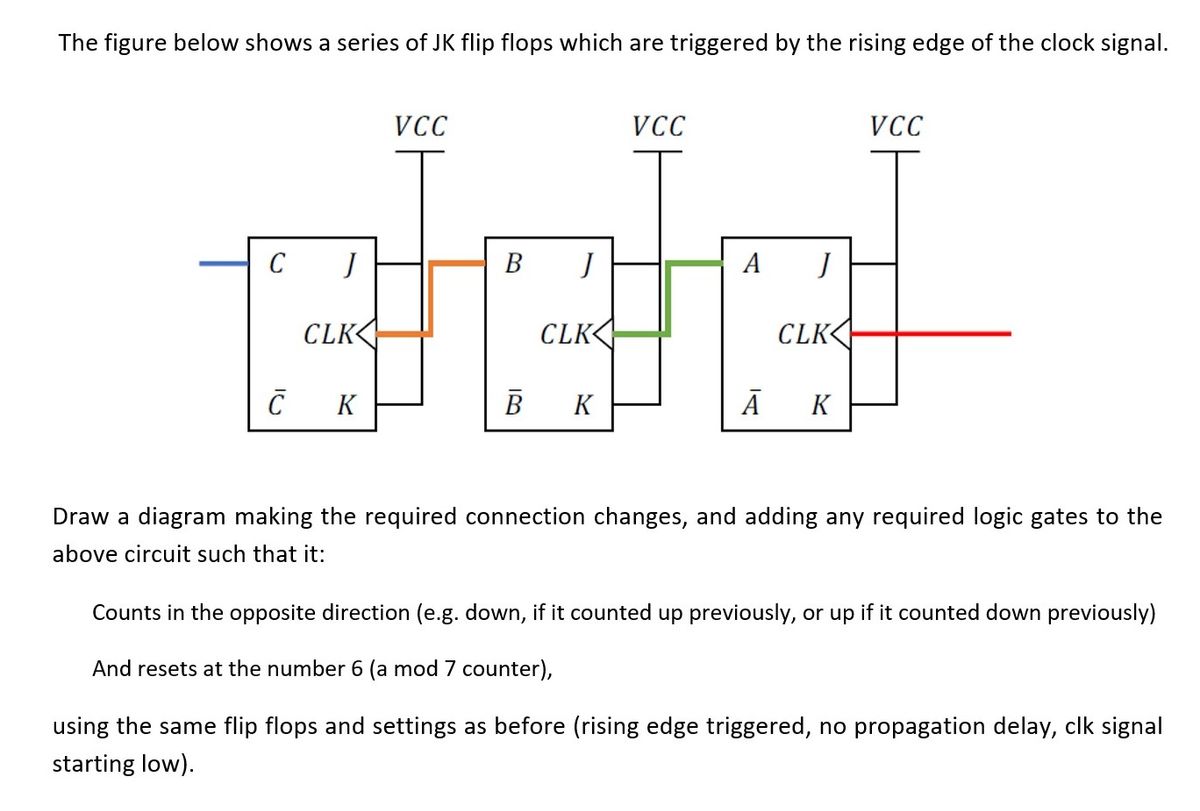

Transcribed Image Text:The figure below shows a series of JK flip flops which are triggered by the rising edge of the clock signal.
VCC
cletel
B
A
CLK
B K
А K
C
C
CLK
K
VCC
CLK
VCC
Draw a diagram making the required connection changes, and adding any required logic gates to the
above circuit such that it:
Counts in the opposite direction (e.g. down, if it counted up previously, or up if it counted down previously)
And resets at the number 6 (a mod 7 counter),
using the same flip flops and settings as before (rising edge triggered, no propagation delay, clk signal
starting low).
Expert Solution
This question has been solved!
Explore an expertly crafted, step-by-step solution for a thorough understanding of key concepts.

Step by stepSolved in 3 steps with 3 images

Knowledge Booster


Learn more about
Need a deep-dive on the concept behind this application? Look no further. Learn more about this topic, electrical-engineering and related others by exploring similar questions and additional content below.Similar questions
- Make a capture of a two-bit down flip flop counter: first counter from 0 to 6 (jumping one) and second counter from 0 to 7 (jumping one) with flip flop jkarrow_forward1) The following waveform are applied to the J-K flip flop with negative edge clock pulse. Assuming the flip flop is initially set, determine the Q output. (a) 2) Repeat question 1 for positive edge clock pulse.arrow_forwardThe question is appended to the image. I don't understand what the question is asking, nor how to implement a d flip flop as required.arrow_forward
- CIK X QFF 6. Complete the timing diagram for outputs QFF and QLATCH given that X and CLK are the input signals for both the D Flip-Flop and the D Latch. clk D D En SET Q CLR Q Q Qarrow_forward1. Explain the set and clear functions on the JK Flip-flop!arrow_forwardPlease help me out. Details are very much appreciated. Latch Flip-flop – Refer to the Waveform number 1. Assuming the initial state is Q = 1, draw the waveform of Q.arrow_forward
arrow_back_ios
arrow_forward_ios
Recommended textbooks for you
- Introductory Circuit Analysis (13th Edition)Electrical EngineeringISBN:9780133923605Author:Robert L. BoylestadPublisher:PEARSON
 Delmar's Standard Textbook Of ElectricityElectrical EngineeringISBN:9781337900348Author:Stephen L. HermanPublisher:Cengage Learning
 Programmable Logic ControllersElectrical EngineeringISBN:9780073373843Author:Frank D. PetruzellaPublisher:McGraw-Hill Education
  Fundamentals of Electric CircuitsElectrical EngineeringISBN:9780078028229Author:Charles K Alexander, Matthew SadikuPublisher:McGraw-Hill Education
 Electric Circuits. (11th Edition)Electrical EngineeringISBN:9780134746968Author:James W. Nilsson, Susan RiedelPublisher:PEARSON
 Engineering ElectromagneticsElectrical EngineeringISBN:9780078028151Author:Hayt, William H. (william Hart), Jr, BUCK, John A.Publisher:Mcgraw-hill Education,
Introductory Circuit Analysis (13th Edition)
Electrical Engineering
ISBN:9780133923605
Author:Robert L. Boylestad
Publisher:PEARSON
Delmar's Standard Textbook Of Electricity
Electrical Engineering
ISBN:9781337900348
Author:Stephen L. Herman
Publisher:Cengage Learning
Programmable Logic Controllers
Electrical Engineering
ISBN:9780073373843
Author:Frank D. Petruzella
Publisher:McGraw-Hill Education
Fundamentals of Electric Circuits
Electrical Engineering
ISBN:9780078028229
Author:Charles K Alexander, Matthew Sadiku
Publisher:McGraw-Hill Education
Electric Circuits. (11th Edition)
Electrical Engineering
ISBN:9780134746968
Author:James W. Nilsson, Susan Riedel
Publisher:PEARSON
Engineering Electromagnetics
Electrical Engineering
ISBN:9780078028151
Author:Hayt, William H. (william Hart), Jr, BUCK, John A.
Publisher:Mcgraw-hill Education,