
Structural Analysis
6th Edition
ISBN: 9781337630931
Author: KASSIMALI, Aslam.
Publisher: Cengage,
expand_more
expand_more
format_list_bulleted
Related questions
Concept explainers
Question
The figure below shows a series of beams with varied supports and connections. The right side of the of the
system includes a rigid beam / column frame. In the grid lines provided below, draw the deflected shape of the
entire system. Assume all members are weightless.
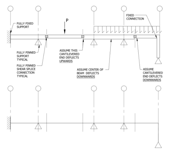

Transcribed Image Text:FIXED
CONNECTION
FULLY FIXED
SUPPORT
ASSUME THIS
FULLY PINNED
SUPPORT
TYPICAL
CANTILEVERED
END DEFLECTS
UPWARDS
FULLY PINNED
SHEAR SPLICE
CONNECTION
TYPICAL
ASSUME
ASSUME CENTER OF
BEAM DEFLECTS
DOWNWARDS
CANTILEVERED
END DEFLECTS
DOWNWARDS
Expert Solution
This question has been solved!
Explore an expertly crafted, step-by-step solution for a thorough understanding of key concepts.

This is a popular solution

Trending nowThis is a popular solution!

Step by stepSolved in 2 steps with 1 images

Knowledge Booster


Learn more about
Need a deep-dive on the concept behind this application? Look no further. Learn more about this topic, civil-engineering and related others by exploring similar questions and additional content below.Similar questions
- Need help asap pls. The beam is shown below. The cross-section of the beam is 250 mm x 400 mm. Take note that the modulus of elasticity of the steel is 200 GPa. Using Moment-Area Method, determine the following: a. Deflection at the right-end of the beam. b. Deflection at the midspan of the beam. Note: Complete solution with figures. Express your intermediate answers with FRACTION and simplify your FINAL answers up to TWO DECIMAL PLACES. BOX your FINAL ANSWERS.arrow_forwardConsider the truss structure in the figure below. All diagonal members have axial stiffness EA, while the chord members have axial stiffness of 2EA. Using unit load method, find the vertical deflection at joint B. Feel free to use a spreadsheet to help with the tedious calculations, but please be sure the calculation steps are well set out.arrow_forwardPlease show answer clear and easy to read and explain the answer if possible thankyou very much in advancearrow_forward
- please show all detailsarrow_forwardUsing Tall = 68 MPa and G= 27 GPa, determine for each of the aluminum bars shown the largest torque T that can be applied and the corresponding angle of twist at end B. Refer to Table 3.1. (a) (b) 45 mm 15 mm 25 mm 25 mm 900 mm B Check my work B The largest torque that can be applied at end B of bar a is N-m and the corresponding angle of twist is The largest torque that can be applied at end B of bar bis N-m and the corresponding angle of twist isarrow_forward
arrow_back_ios
arrow_forward_ios
Recommended textbooks for you
 Structural Analysis (10th Edition)Civil EngineeringISBN:9780134610672Author:Russell C. HibbelerPublisher:PEARSON
 Principles of Foundation Engineering (MindTap Cou...Civil EngineeringISBN:9781337705028Author:Braja M. Das, Nagaratnam SivakuganPublisher:Cengage Learning
 Fundamentals of Structural AnalysisCivil EngineeringISBN:9780073398006Author:Kenneth M. Leet Emeritus, Chia-Ming Uang, Joel LanningPublisher:McGraw-Hill Education
 Traffic and Highway EngineeringCivil EngineeringISBN:9781305156241Author:Garber, Nicholas J.Publisher:Cengage Learning
Structural Analysis (10th Edition)
Civil Engineering
ISBN:9780134610672
Author:Russell C. Hibbeler
Publisher:PEARSON
Principles of Foundation Engineering (MindTap Cou...
Civil Engineering
ISBN:9781337705028
Author:Braja M. Das, Nagaratnam Sivakugan
Publisher:Cengage Learning
Fundamentals of Structural Analysis
Civil Engineering
ISBN:9780073398006
Author:Kenneth M. Leet Emeritus, Chia-Ming Uang, Joel Lanning
Publisher:McGraw-Hill Education
Traffic and Highway Engineering
Civil Engineering
ISBN:9781305156241
Author:Garber, Nicholas J.
Publisher:Cengage Learning