
Introductory Circuit Analysis (13th Edition)
13th Edition
ISBN: 9780133923605
Author: Robert L. Boylestad
Publisher: PEARSON
expand_more
expand_more
format_list_bulleted
Related questions
Concept explainers
Question
Please solve this problem I do not understand If my answer is true, solve it clearly please as my question is clear.
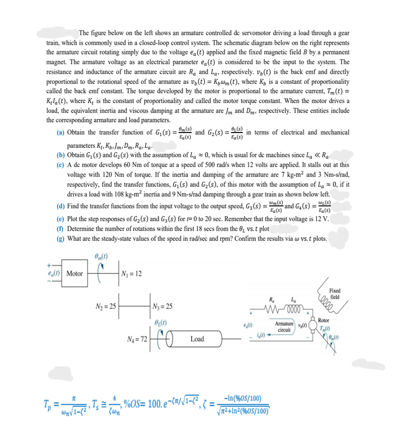

Transcribed Image Text:The figure below on the left shows an armature controlled de servomotor driving a load through a gear
train, which is commonly used in a closed-loop control system. The schematic diagram below on the right represents
the armature circuit rotating simply due to the voltage ea(t) applied and the fixed magnetic field B by a permanent
magnet. The armature voltage as an electrical parameter ea(t) is considered to be the input to the system. The
resistance and inductance of the armature circuit are R₁ and La, respectively. v(t) is the back emf and directly
proportional to the rotational speed of the armature as v₁ (t) = K₁@m(t), where K₁ is a constant of proportionality
called the back emf constant. The torque developed by the motor is proportional to the armature current, Tm(t) =
Kela(t), where K₂ is the constant of proportionality and called the motor torque constant. When the motor drives a
load, the equivalent inertia and viscous damping at the armature are Jm and Dm, respectively. These entities include
the corresponding armature and load parameters.
(a) Obtain the transfer function of G₁(s) = m(s) and G₂ (s) = (s) in terms of electrical and mechanical
Ea(s)
Ea(s)
parameters Kt, Kp. Jm, DmRa, La
(b) Obtain G₁ (s) and G₂ (s) with the assumption of La≈ 0, which is usual for de machines since La << Ra
(c) A de motor develops 60 Nm of torque at a speed of 500 rad/s when 12 volts are applied. It stalls out at this
voltage with 120 Nm of torque. If the inertia and damping of the armature are 7 kg-m² and 3 Nm-s/rad,
respectively, find the transfer functions, G₁ (s) and G₂ (s), of this motor with the assumption of La ≈ 0, if it
drives a load with 108 kg-m² inertia and 9 Nm-s/rad damping through a gear train as shown below left.
WL(S)
(d) Find the transfer functions from the input voltage to the output speed, G3 (s) = m(s) and G4(s) =
Ea(s)
(e) Plot the step responses of G₂ (s) and G3 (s) for t=0 to 20 sec. Remember that the input voltage is 12 V.
(f) Determine the number of rotations within the first 18 secs from the 0₁ vs. t plot
(g) What are the steady-state values of the speed in rad/sec and rpm? Confirm the results via w vs. t plots.
0(1)
e(t) Motor
N₂=25
N₁ = 12
|N₂=25
0₂(1)
172| O
N₁ = 72
Load
(1)
11
=₁1-²› Ts = %= 100.6
- %OS= 100.e-²/√¹-²₁ = ₁
wn√/1-8²
ζωη
Ra
L₂
M0000
4(0)-
-In (%05/100)
√²+In²(%60S/100)
Armature (1)
circuit
0000
Rotor
T (1)
(1)
Expert Solution
This question has been solved!
Explore an expertly crafted, step-by-step solution for a thorough understanding of key concepts.
Step 1: Given
VIEW Step 2: Determination of transfer functions
VIEW Step 3: Determination of transfer functions
VIEW Step 4: Consideration of given assumption
VIEW Step 5: Calculations of transfer functions' parameters
VIEW Step 6: Transfer functions when output is speed
VIEW Step 7: Step responses
VIEW Step 8: Calculation of number of rotations and steady-state speed.
VIEW Solution
VIEW 
Step by stepSolved in 9 steps with 3 images

Knowledge Booster


Learn more about
Need a deep-dive on the concept behind this application? Look no further. Learn more about this topic, electrical-engineering and related others by exploring similar questions and additional content below.Similar questions
- Given: The circuit in Figure 1 Find: The truth table for F(A,B,C,D). OPERT Figure 1: The circuit diagram for the function F(A,B,C,D) used in this problem. D F(A,B,C,D)arrow_forwardplease solve this question clearly and perfectly with explanation. I need solution within one hour from now. I will sure like solution and will rate up the work. thanksarrow_forward35. What is the group of 1s present in 8 cells of a K- map called? a) Pair b) Quad c) Octet d) Octavearrow_forward
- Note: Don't use chatGPT or google or any other source to copy paste. I will dislike the solution if you do so.I need unique solution. if you are not able to solve please let other expert review. The given diagram represents a sequential circuit. This circuit has a single input labeled "x" and a single output labeled "Z." It also has two state variables called Q1 and Q2, which together can have four different combinations of present states: 00, 01, 10, and 11.Create the state table and state diagramand boolean equation as well.arrow_forwardRead and solve carefully please write clearly and box the final answerarrow_forwardKindly provide a COMPLETE and CLEAR solution. Answer it ASAP because I really need it right now. Answer should be typewritten. Instructions: Write the complete solution of the example given in the photo.arrow_forward
arrow_back_ios
arrow_forward_ios
Recommended textbooks for you
- Introductory Circuit Analysis (13th Edition)Electrical EngineeringISBN:9780133923605Author:Robert L. BoylestadPublisher:PEARSON
 Delmar's Standard Textbook Of ElectricityElectrical EngineeringISBN:9781337900348Author:Stephen L. HermanPublisher:Cengage Learning
 Programmable Logic ControllersElectrical EngineeringISBN:9780073373843Author:Frank D. PetruzellaPublisher:McGraw-Hill Education
  Fundamentals of Electric CircuitsElectrical EngineeringISBN:9780078028229Author:Charles K Alexander, Matthew SadikuPublisher:McGraw-Hill Education
 Electric Circuits. (11th Edition)Electrical EngineeringISBN:9780134746968Author:James W. Nilsson, Susan RiedelPublisher:PEARSON
 Engineering ElectromagneticsElectrical EngineeringISBN:9780078028151Author:Hayt, William H. (william Hart), Jr, BUCK, John A.Publisher:Mcgraw-hill Education,
Introductory Circuit Analysis (13th Edition)
Electrical Engineering
ISBN:9780133923605
Author:Robert L. Boylestad
Publisher:PEARSON
Delmar's Standard Textbook Of Electricity
Electrical Engineering
ISBN:9781337900348
Author:Stephen L. Herman
Publisher:Cengage Learning
Programmable Logic Controllers
Electrical Engineering
ISBN:9780073373843
Author:Frank D. Petruzella
Publisher:McGraw-Hill Education
Fundamentals of Electric Circuits
Electrical Engineering
ISBN:9780078028229
Author:Charles K Alexander, Matthew Sadiku
Publisher:McGraw-Hill Education
Electric Circuits. (11th Edition)
Electrical Engineering
ISBN:9780134746968
Author:James W. Nilsson, Susan Riedel
Publisher:PEARSON
Engineering Electromagnetics
Electrical Engineering
ISBN:9780078028151
Author:Hayt, William H. (william Hart), Jr, BUCK, John A.
Publisher:Mcgraw-hill Education,