Delmar's Standard Textbook Of Electricity
7th Edition
ISBN: 9781337900348
Author: Stephen L. Herman
Publisher: Cengage Learning
expand_more
expand_more
format_list_bulleted
Concept explainers
Question
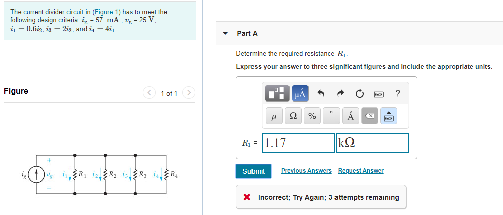
I am taking Electric Circuits and using the 10th edition nilson reidel. Looking at the question attached. I used KCL to find i1 to be 21.375 mA, and suspect that V1 should be the same as Vg, but its not working out. Is there something I'm missing?
Thanks.

Transcribed Image Text:The current divider circuit in (Figure 1) has to meet the
following design criteria: ig = 57 mA , vg = 25 V,
i1 = 0.6i2, iz = 2i2, and i4 = 4i1.
Part A
Determine the required resistance R1.
Express your answer to three significant figures and include the appropriate units.
Figure
<) 1 of 1>
HA
Ω
X)
R1 = 1.17
Submit
Previous Answers Request Answer
i(1) iR, iR2 is,R3 isR4
X Incorrect; Try Again; 3 attempts remaining
Expert Solution
This question has been solved!
Explore an expertly crafted, step-by-step solution for a thorough understanding of key concepts.
This is a popular solution
Trending nowThis is a popular solution!
Step by stepSolved in 4 steps with 6 images

Knowledge Booster
Learn more about
Need a deep-dive on the concept behind this application? Look no further. Learn more about this topic, electrical-engineering and related others by exploring similar questions and additional content below.Similar questions
- Kindly answer all of the questions please, I will rate you with like/upvote. Please answer all of the questions. Thank you so much.arrow_forwardI need help understanding this question, what does this question is talking aboutarrow_forwardUsing the rules for parallel circuits and Ohmslaw, solve for the missing values. ETE1E2E3E4ITl1I2l33.2AI4RT3.582R116R210R3R420PTP1P2P3P4arrow_forward
- Convert the wiring diagram below into a circuit (schematic) diagram using standard symbols.arrow_forwardTrue False 0000000 ☐ ☐ ☐ ☐ ☐ ☐ ☐ Are the following statements about unloaded voltage dividers true or false? A voltage divider is a series connection of resistors. A voltage divider is a parallel connection of resistors. In a voltage divider, the currents through the resistors are equal. In a voltage divider, the currents through the resistors behave like the ratio of the resistors. In a voltage divider, the currents through the resistors behave like the ratio of the reciprocal values of the resistors. In a voltage divider, the voltages across the resistors are equal. In a voltage divider, the voltages across the resistors behave like the ratio of the resistors. In a voltage divider, the voltages across the resistors behave like the ratio of the reciprocal values of the resistors. П ☐arrow_forwardUse multismarrow_forward
- A voltage divider consists of a 3000 – ohm, a 5000 – ohm, and 10000 – ohm resistor in series and the series current is 15 mA. Find (a) the voltage drop across each resistance and (b) the total voltage.arrow_forwardA secondary cell having an e.m.f. of 2V and an internal resistance of 1 ohm is connected in serieswith a primary cell having an e.m.f. of 1.5V and an internal resistance of 100 ohm. The negativeterminal of each cell is connected to the positive terminal of the other cell. A voltmeter having aresistance of 50 ohm is connected to measure the terminal voltage of the cells. Calculate the voltmeterreading and the current in each cell.arrow_forwardWhich statement is correct about a series circuit? The sum of currents in each load multiplied by the total resistance determines t voltage. The sum of the individual resistances equals the total resistance. The sum of all the voltage drops equals the source voltage. The voltage drops are equal to the input source. In a series circuit, the current, I, is Different in each resistor The highest near the positive and negative terminals of the voltage source The same everywhere Different at all points along the circuitarrow_forward
- 6arrow_forwardEmploying the characteristic curve in Figure 1 and obtain the design for a voltage divider configuration that has a Q point of ICQ = 5 mA and VCEQ = 8 V. Using VCC = 24 V and RC = 3RE. Find the following: a) Draw the configuration indicating each of the elements b) Determine RC and RE c) Find VE d) Determine VB e) Calculate ? for point Q f) Find R2 if R1 = 24 kΩarrow_forwardNow, double the value of R1 and R2. Disconnect the load and make sure that VNL (No Load) is the same as the original circuit. Then repeat the VOUT measurements for load values of 50 Ohm and 500 Ohm. Was the loaded voltage divider more stable or less stable than the original circuit? (In the book it provides the current values but in the problem it provides no current ranges) This relates to voltage divider stability. I think its asking me to compare the stability of the No Load circuit with the Resistor Load circuit.arrow_forward
arrow_back_ios
SEE MORE QUESTIONS
arrow_forward_ios
Recommended textbooks for you
 Delmar's Standard Textbook Of ElectricityElectrical EngineeringISBN:9781337900348Author:Stephen L. HermanPublisher:Cengage Learning

Delmar's Standard Textbook Of Electricity
Electrical Engineering
ISBN:9781337900348
Author:Stephen L. Herman
Publisher:Cengage Learning