Steel Design (Activate Learning with these NEW titles from Engineering!)
6th Edition
ISBN: 9781337094740
Author: Segui, William T.
Publisher: Cengage Learning
expand_more
expand_more
format_list_bulleted
Concept explainers
Question
thumb_up100%

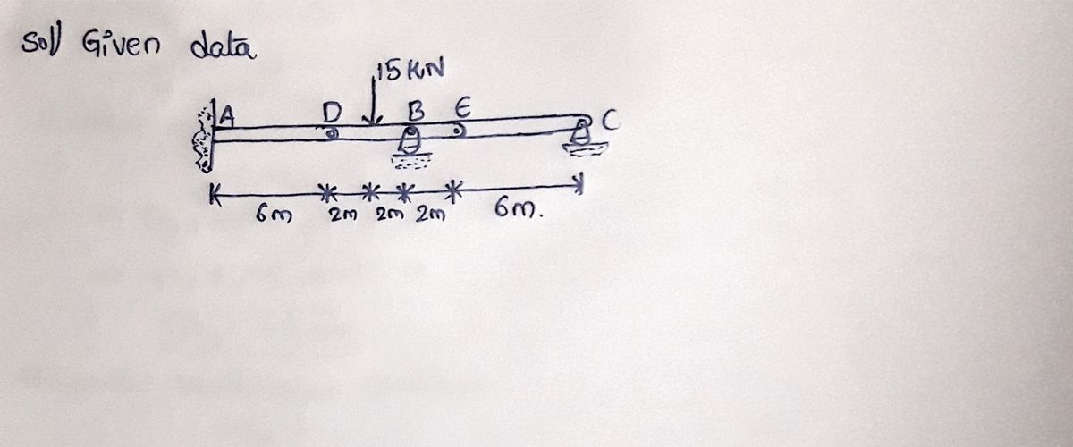
Transcribed Image Text:The compound beam is fixed at A and supported by a rocker
At B and C. There are hinges (pins) at D and E. Determine
the reactions at the supports.
A
-6 m
D
15 kN
2
B E
m2 m2 m
6 m
Expert Solution
arrow_forward
Step 1

Step by stepSolved in 3 steps with 3 images

Knowledge Booster
Learn more about
Need a deep-dive on the concept behind this application? Look no further. Learn more about this topic, civil-engineering and related others by exploring similar questions and additional content below.Similar questions
- Circle all the trusses below which are solvable in Statics (hence stable, externally determinant, andinternally determinate)arrow_forwardThe 2014-T6 aluminum rod AC is reinforced with the firmly bonded A992 steel tube BC. If the assembly fits snugly between the rigid supports so that there is no gap at C, determine the support reactions when the axial force of400 kN is applied. The assembly is attached to D.arrow_forwardStatics - Zero Force Members1. Identify the zero-force members in the truss shown. 2. Redraw the truss without the zero-force members included.arrow_forward
- The rigid bar AB is pinned at A and supported by two aluminum rods CG and DH, each having a diameter of 25mm and elastic modulus of EAI = 70 GPa. Determine a) The force in each rod when the 20 kN load is applied. b) The axial deformation (elongation) of rod CG c) The axial deformation (elongation) of rod DH H. 1-0 0-5 A 0-6' 1.2M L 0-8 20KNarrow_forwardDetermine the force in each member of the truss shown by the method of joints and/or sectionarrow_forward-5 @ 3m-15m- C F H J K ML boo I A 4@4m=16m B D G E 60 kips A For the truss shown, what is the force in member FG? B what is the force in member BE? + --Darrow_forward
- 954. The 2014-T6 aluminum rod AC is reinforced with the firmly bonded A992 steel tube BC. When no laad is applied to the assembly, the gap between end C and the rigid support is 0.5 mm. Determine the support reactions when the axial force of 400 kN is applied. 400 mm 400 kN A992 steel So mm S00 mm 25 mi2014-T6 aluminum alloy Section a-aarrow_forwardThe rigid member is held in the position show by three steel tie rods. Each rod has an unstretched length of 0.75mm and a cross?sectional area of 125 mm2. Find the forces in the rods if the turnbuckle on rod EF undergoes one full turn. The lead of the screw is 1.75 mm (the lead of the screw would cause the rod to shorten (when unloaded) by 1.75 mm when the turnbuckle is rotated 1 revolution. Esteel: 200 GPa. USE THE FORCE METHOD TO SOLVE 0.75 m B A-0.5 m -0.5 m-C 0.75 m What is the force in member EF? What is the force in member AB? =arrow_forwardTHE DIAGONAL MEMBERS IN THE CENTER PANELS OF THE TRUSS SHOWN ARE VERY SLENDER AND CAN ACT ONLY IN TENSION; SUCH MEMBERS ARE KNOWN AS COUNTERS. DETERMINE THE FORCE IN MEMBER DE AND IN THE COUNTERS THAT ARE ACTING UNDER THE GIVEN LOADING. (15 PTS) Counters ARA B F 6 ft H C E G 3 kips 6 kips 9 kips -S ft- <8 ft- S ft→|<-S ft-arrow_forward
- (c) The rigid bar ABC is suspended from three wires of the same material. The cross- sectional area of the wire at B is equal to half of the cross-sectional area of the wires at A and C. Determine the tension in each wire caused by the load P shown. ----|--²--| A 9 DAB T L P Fig. Q1(c) PL Hint: S = note that ABC is a rigid bar. EA Carrow_forwardAxial deformationarrow_forwardA steel pipe (1) is attached to an aluminum pipe (2) at flange B. The pipes are attached to rigid supports at A and C, respectively 18 m 14 m Member (a) has a cross-sectional area A,-3,600 mm2, an elastic modul as a cross-sectional area A 3,600 mm2, an elastic modulus E-200 GPa, and an allowable has a cross-sectional area A2 2,o00 mm2, an elastie modulus E-70 GPa, and an allowable normal stress of 120 MPa. Determine the maximum load Pthat can be applied to fange B without exceeding either allowable stressarrow_forward
arrow_back_ios
SEE MORE QUESTIONS
arrow_forward_ios
Recommended textbooks for you
 Steel Design (Activate Learning with these NEW ti...Civil EngineeringISBN:9781337094740Author:Segui, William T.Publisher:Cengage Learning

Steel Design (Activate Learning with these NEW ti...
Civil Engineering
ISBN:9781337094740
Author:Segui, William T.
Publisher:Cengage Learning