Delmar's Standard Textbook Of Electricity
7th Edition
ISBN: 9781337900348
Author: Stephen L. Herman
Publisher: Cengage Learning
expand_more
expand_more
format_list_bulleted
Question
thumb_up100%

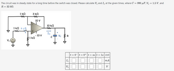
Transcribed Image Text:The circuit was in steady state for a long time before the switch was closed. Please calculate V₂ and I, at the given times, where C = 990 µF, V₂ = 1.5 V, and
R = 32 kN.
1 ΚΩ
w
3 ΚΩ
w
Vs
1 ΚΩ + = 0
ww
10 V
10 ΚΩ
w
Io
- 10 V
Vc
R
C
1 ΚΩ
I₁
|t=0|t=0+ t = ∞ot = 1s | Unit
m.A
Ve 010
V
Expert Solution
This question has been solved!
Explore an expertly crafted, step-by-step solution for a thorough understanding of key concepts.
This is a popular solution
Trending nowThis is a popular solution!
Step by stepSolved in 2 steps with 4 images

Knowledge Booster
Similar questions
- For the circuit in the figurea) Determine the time constant.b) Write the mathematical expression for IL, VL and VR, after the switch is closed.c) Determine IL, VL for one, three and five time constants.d) Draw the waveforms of IL, VL and VR.arrow_forwardFor the circuit shown in the figure, ϵ0=100Volt, R1=50Ω, R2=100Ω, C=2μF. What is the status of the capacitor immediately after the switch is closed, charged or discharged, and what is the initial current of the battery immediately after the switch is closed?arrow_forwardPlz solve within 30min I vill give definitely upvote and vill give positive feedback thank youarrow_forward
- in the image below, Please find the voltage across the resistor at time t = 0.00069 seconds. The energy stored in the capacitor and inductor at t=0 is 0 Joules. The values are I1 = 75 A, R = 0.059 ohms, L = 0.01 Henries, C = 0.04 Farads.arrow_forwardIn the circuit below, Find the voltage across the inductor at time t = 0.000909 s. The values are V1 = 146V, R = 4.4 ohms, L =0.02 henriesarrow_forward1. A purely resistive circuit the current is leading by 90° with respect to voltage. 2. A purely inductive circuit the current is lag behind the voltage by 90°. 3. A purely capacitive circuit the current is lead by 90° with respect to the voltage. 4. A capacitor element stored magnetic energy. 5. An inductor element stored electrical energy. 6. Resistor elements consume power. 7. Angle between current and voltage is called power. 8. The power factor angle for a purely resistive is zero. 9. The power factor angle for a purely inductive load is -90°. 10. The power factor of a purely capacitive is leading.arrow_forward
- = Using Kirchhoff's rules, find the following. (₁ = 70.9 V, 8₂= 60.7 V, and 83 1 E₁ R₂ E₂ 4.00 ΚΩ www R₂ 3.00 ΚΩ d E₁ 2.00 ΚΩ www R₁ (a) the current in each resistor shown in the figure above (b) the potential difference between points c and f 79.1 V.)arrow_forwardWith V1, voltage peak to peak is 10 volts, R1=200 Ohm, R2=1000 Ohm and C1= 300 nF. Find Vx, voltage across the the capacitor, C1 and R2 when the frequency is 1000 Hz and 10000 Hzarrow_forwardIf a circuit has a resistance of 3002 and a series inductance of 5002, what is the relationship between the applied circuit voltage and the circuit current? The applied voltage lags the circuit current. The phase shift between the circuit voltage and current changes with time. The applied voltage is in phase with the circuit current. The applied voltage leads the circuit cur Previous Page Next Page Page 2 of 10arrow_forward
- When the switch is in position 1, the circuit will charge the capacitor. Find the Thevenin Equivalent Circuit for the charge phase and determine the time constant (Rh*C) for the charge phase.arrow_forwardRC Circuits VII Each circuit below consists of a battery, a capacitor and several resistors. Assume the capacitor is initially uncharged. Determine the voltage and current of each resistor, the voltage and charge of the capacitor and the current thru the battery. All answers are whole numbers. Indicate the direction of each current. (a) The switch has just been closed. 252V ΙΩ L D 122 ww www ΙΩ A D 122 www ἸΩ A 2F (b) The switch has been closed for a long time. 252V www 152 B 2F 292 a B ww 252 www (e) The switch has been closed for a long time. A 252 B. 202 ww fump 192 202 2F 56Varrow_forwardThe capacitors in the figure are discharged when closing the switch. The switch closes at t = 0.Your University ID has 7 digits: X6X5X4X3X2X1X0Y1 = first digit from right to left (X0, X1, ...) that is different from zero.Y2 = second digit from right to left that is different from zero.Y3 = third digit from right to left that is different from zero.Y4 = fourth digit from right to left that is different from zero.Use the following values for the different components (a) Find the time constant of the circuit.(b) Find the charge on each of the capacitors as a function of time.arrow_forward
arrow_back_ios
SEE MORE QUESTIONS
arrow_forward_ios
Recommended textbooks for you
 Delmar's Standard Textbook Of ElectricityElectrical EngineeringISBN:9781337900348Author:Stephen L. HermanPublisher:Cengage Learning

Delmar's Standard Textbook Of Electricity
Electrical Engineering
ISBN:9781337900348
Author:Stephen L. Herman
Publisher:Cengage Learning