Introductory Circuit Analysis (13th Edition)
13th Edition
ISBN: 9780133923605
Author: Robert L. Boylestad
Publisher: PEARSON
expand_more
expand_more
format_list_bulleted
Question
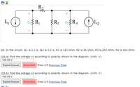
Q6. In the circuit, Is1 is 2.1 A, Is2 is 3.2 A, R1 is 123 Ohm, R2 is 26 Ohm, R3 is 245 Ohm, R4 is 360 Ohm.
(Q6.a) Find the voltage v1 according to polarity shown in the diagram. (Unit: V)
(Q6.b) Find the voltage v2 according to polarity shown in the diagram. (Unit: V)

Transcribed Image Text:**Circuit Diagram Explanation and Problem Solution**
The circuit diagram shown consists of two current sources and four resistors. The components are labeled as follows:
- Current Sources:
- \(I_{S1} = 2.1 \, \text{A}\)
- \(I_{S2} = 3.2 \, \text{A}\)
- Resistors:
- \(R_1 = 123 \, \Omega\)
- \(R_2 = 26 \, \Omega\)
- \(R_3 = 245 \, \Omega\)
- \(R_4 = 360 \, \Omega\)
The circuit includes two voltages to be determined:
- \(v_1\) across \(R_1\)
- \(v_2\) across \(R_4\)
**Q6. Problem Statement:**
In the circuit provided:
- Find the voltage \(v_1\) according to the polarity shown in the diagram.
- Find the voltage \(v_2\) according to the polarity shown in the diagram.
**(Q6.a) Solution Attempt:**
- Calculated \(v_1 = -108.05 \, \text{V}\)
- Status: Incorrect
- Tries: 1/5
**(Q6.b) Solution Attempt:**
- Calculated \(v_2 = -108.05 \, \text{V}\)
- Status: Incorrect
- Tries: 1/5
Note: The attempts were marked incorrect, indicating a need to reassess either the calculation or the method applied.
Expert Solution
This question has been solved!
Explore an expertly crafted, step-by-step solution for a thorough understanding of key concepts.
This is a popular solution
Trending nowThis is a popular solution!
Step by stepSolved in 2 steps with 1 images

Knowledge Booster
Similar questions
- 3Draw the circuit diagram an solve using ohms law asap pls 3. Two lamps rated 100W and 200V areconnected in series across 200V supply . Find the power consumed by each lamparrow_forwardShown in the figure below is an electrical circuit containing three resistors and two batteries. I₁ 0= 4 + L . ww R3 R₂ ww 1₂ R₁ ww Write down the Kirchhoff Junction equation and solve it for I, in terms of I₂ and I3. Write the result here: 1₁ = 12-13 R₂=552 R₂ = 132 13 Write down the Kirchhoff Loop equation for a loop that starts at the lower left corner and follows the perimeter of the circuit diagram clockwise. - IzR3 − LR₁ + 14 + 10 Write down the Kirchhoff Loop equation for a loop that starts at the lower left corner and touches the components 4V, R₂, and R₁. 0 = 4-1₂R₂-11R₁ The resistors in the circuit have the following values: R₁ = 12 Solve for all the following (some answers may be negative): I₁ = 27.78 X Amperes 1₂ = 28.84 X Amperes 13 = 1.060 X Amperes NOTE: For the equations, put in resistances and currents SYMBOLICALLY using variables like R₁,R₂,R3 and 11,12,13. Use numerical values of 10 and 4 for the voltages.arrow_forwardFrom Figure 1 above find Rth (BC) a. 4.24 b. 8.55O c. 6.86O d. 5.56arrow_forward
Recommended textbooks for you
 Introductory Circuit Analysis (13th Edition)Electrical EngineeringISBN:9780133923605Author:Robert L. BoylestadPublisher:PEARSON
 Delmar's Standard Textbook Of ElectricityElectrical EngineeringISBN:9781337900348Author:Stephen L. HermanPublisher:Cengage Learning
 Programmable Logic ControllersElectrical EngineeringISBN:9780073373843Author:Frank D. PetruzellaPublisher:McGraw-Hill Education
 Fundamentals of Electric CircuitsElectrical EngineeringISBN:9780078028229Author:Charles K Alexander, Matthew SadikuPublisher:McGraw-Hill Education
 Electric Circuits. (11th Edition)Electrical EngineeringISBN:9780134746968Author:James W. Nilsson, Susan RiedelPublisher:PEARSON
 Engineering ElectromagneticsElectrical EngineeringISBN:9780078028151Author:Hayt, William H. (william Hart), Jr, BUCK, John A.Publisher:Mcgraw-hill Education,

Introductory Circuit Analysis (13th Edition)
Electrical Engineering
ISBN:9780133923605
Author:Robert L. Boylestad
Publisher:PEARSON

Delmar's Standard Textbook Of Electricity
Electrical Engineering
ISBN:9781337900348
Author:Stephen L. Herman
Publisher:Cengage Learning

Programmable Logic Controllers
Electrical Engineering
ISBN:9780073373843
Author:Frank D. Petruzella
Publisher:McGraw-Hill Education

Fundamentals of Electric Circuits
Electrical Engineering
ISBN:9780078028229
Author:Charles K Alexander, Matthew Sadiku
Publisher:McGraw-Hill Education

Electric Circuits. (11th Edition)
Electrical Engineering
ISBN:9780134746968
Author:James W. Nilsson, Susan Riedel
Publisher:PEARSON

Engineering Electromagnetics
Electrical Engineering
ISBN:9780078028151
Author:Hayt, William H. (william Hart), Jr, BUCK, John A.
Publisher:Mcgraw-hill Education,