
Introductory Circuit Analysis (13th Edition)
13th Edition
ISBN: 9780133923605
Author: Robert L. Boylestad
Publisher: PEARSON
expand_more
expand_more
format_list_bulleted
Related questions
Question
Solve b
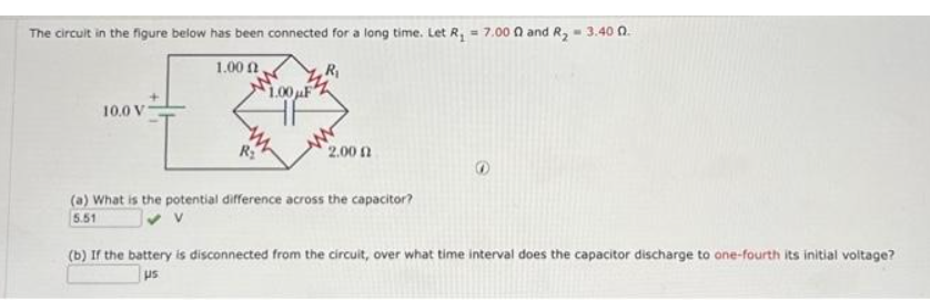

Transcribed Image Text:The circuit in the figure below has been connected for a long time. Let R₁ = 7.000 and R₂ = 3.40 0.
1.000,
10.0 V
f
R₂
$1.00μF
2.00 (2
(a) What is the potential difference across the capacitor?
5.51
(b) If the battery is disconnected from the circuit, over what time interval does the capacitor discharge to one-fourth its initial voltage?
us
Expert Solution
This question has been solved!
Explore an expertly crafted, step-by-step solution for a thorough understanding of key concepts.

This is a popular solution
Step 1: Summarize the data.
VIEW Step 2: Determine the equivalent resistance across the capacitor for t>0.
VIEW Step 3: Determine the expression of voltage across the capacitor, VC(t).
VIEW Step 4: Determine the time interval does the capacitor voltage reaches to one-fourth of it's initial voltage
VIEW Solution
VIEW 
Trending nowThis is a popular solution!

Step by stepSolved in 5 steps with 4 images

Knowledge Booster


Learn more about
Need a deep-dive on the concept behind this application? Look no further. Learn more about this topic, electrical-engineering and related others by exploring similar questions and additional content below.Similar questions
- Hello Sir.Good Night. I have a question in my home work related Control System Lesson. The following below is my question.Please advise, Thank you so much.arrow_forwardQ4) Draw the IC's diagram of the circuit shown below using the required 74 series DODA B D LLarrow_forwardAn induction motor is represented as a line diagram and an equivalent circuit. Find: A. The number of poles B. The synchronous speed of the stator field C. The sliparrow_forward
- I need an expert solution in MATLAB language for the question, and I need the solution to be using MATLAB and in the form of an image. I do not need any notes with the program, just an explanation at the end of the image. By the way, two questions. Q2. Write a MATLAB user-defined function, freefall(), that computes the velocity and the distance of a free fall object. The velocity and the distance of a free fall object can be written as: v = gt y = yo+gt² where yo is the initial position, t is the time travelled and g is the acceleration due to gravity (- 9.81 m/s2). Note that the initial position can only be a scalar value. Q7. Write a user-defined MATLAB Function for the following math function: ((xy-5)² z = if x, y > 0 elsewhere The inputs to the function are x and y, where the output is z. Write the function such that x and y can be vectors. I. II. Use the function to calculate z(3,4) and z(5, -7). Use the function to make a colored 3D plot of the function z for -5arrow_forward1/C1 1/C2a 1/C2b 1/C3a 1/C3b OTR O PRE D 74574N/1 CLK O CLR O PRE O PRE D 74574N/ CLK O CLR Q Q Q O PRE R. DIS S55 THRO PASTAN/1 74574N/2 CLK Q 74574N/2 CLK Q CV GRD V+ a CLR O CLR 100µF LED2 7 LED3 V LED4 V LEDS A V LED1 wwD ww ww wwarrow_forwardProblem #14. Find V2.arrow_forward
- Identify the states, inputs, and output • Show your work to get the dynamics • Present the state space model, including the state equations and output equationarrow_forwardAn electric toothbrush has a base designed to hold the toothbrush handle when not in use. As shown, the handle has a cylindrical hole that fits loosely over a matching cylinder on the base. When the handle is placed on the base, a changing current in a solenoid inside the base cylinder induces a current in a coil inside the handle. This induced current charges the battery in the handle. We can model the base as a solenoid of length ℓ with NB turns (as shown), carrying a current i, and having a cross-sectional area A. The handle coil contains NH turns and completely surrounds the base coil. Find the mutual inductance of the system.arrow_forwardTwo coils are placed close to each other as shown in the figure. The coil on the left is connected to a battery and a switch, and the coil on the right is connected to a resistor.What is the direction of the current in the resistori. an instant after closing the switch?ii. after the switch has been closed for several seconds?iii. an instant after opening the switch?Choose your answers betweento. on the leftb. on the rightc. the current is zero.And clearly explain the reason for your answer.arrow_forward
arrow_back_ios
arrow_forward_ios
Recommended textbooks for you
- Introductory Circuit Analysis (13th Edition)Electrical EngineeringISBN:9780133923605Author:Robert L. BoylestadPublisher:PEARSON
 Delmar's Standard Textbook Of ElectricityElectrical EngineeringISBN:9781337900348Author:Stephen L. HermanPublisher:Cengage Learning
 Programmable Logic ControllersElectrical EngineeringISBN:9780073373843Author:Frank D. PetruzellaPublisher:McGraw-Hill Education
  Fundamentals of Electric CircuitsElectrical EngineeringISBN:9780078028229Author:Charles K Alexander, Matthew SadikuPublisher:McGraw-Hill Education
 Electric Circuits. (11th Edition)Electrical EngineeringISBN:9780134746968Author:James W. Nilsson, Susan RiedelPublisher:PEARSON
 Engineering ElectromagneticsElectrical EngineeringISBN:9780078028151Author:Hayt, William H. (william Hart), Jr, BUCK, John A.Publisher:Mcgraw-hill Education,
Introductory Circuit Analysis (13th Edition)
Electrical Engineering
ISBN:9780133923605
Author:Robert L. Boylestad
Publisher:PEARSON
Delmar's Standard Textbook Of Electricity
Electrical Engineering
ISBN:9781337900348
Author:Stephen L. Herman
Publisher:Cengage Learning
Programmable Logic Controllers
Electrical Engineering
ISBN:9780073373843
Author:Frank D. Petruzella
Publisher:McGraw-Hill Education
Fundamentals of Electric Circuits
Electrical Engineering
ISBN:9780078028229
Author:Charles K Alexander, Matthew Sadiku
Publisher:McGraw-Hill Education
Electric Circuits. (11th Edition)
Electrical Engineering
ISBN:9780134746968
Author:James W. Nilsson, Susan Riedel
Publisher:PEARSON
Engineering Electromagnetics
Electrical Engineering
ISBN:9780078028151
Author:Hayt, William H. (william Hart), Jr, BUCK, John A.
Publisher:Mcgraw-hill Education,