Introductory Circuit Analysis (13th Edition)
13th Edition
ISBN: 9780133923605
Author: Robert L. Boylestad
Publisher: PEARSON
expand_more
expand_more
format_list_bulleted
Concept explainers
Question
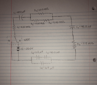
The circuit displayed below is comprised of resistors, a battery, capacitors and a single pole double throwswitch (SPDT). When switch is in the position of A, the battery is connected to the circuit. When the switch is in the position of B, the battery is then replaced with a wire.
In the beginning, the switch is open, and all capacitors are firstly uncharged. The switch is then flipped in the position of A, so the battery is in the circuit. Then, 30.0 seconds after the switch is then submitted to the position of A, what will the potential difference be beyond C3?

Transcribed Image Text:R2=20.0 ML
S=140.0uF
3=75,00 M_A
Ry=9,00M
ZR-8.00MA
(z=95.0 UF
AT SPDT
E = 100.0V
R5=11.5 M
Cy=21.0,uF (3= 40.0,MF
(एु3 LO O 4
Cg=1b.5 MF
Expert Solution
This question has been solved!
Explore an expertly crafted, step-by-step solution for a thorough understanding of key concepts.
Step by stepSolved in 3 steps with 3 images

Knowledge Booster
Learn more about
Need a deep-dive on the concept behind this application? Look no further. Learn more about this topic, electrical-engineering and related others by exploring similar questions and additional content below.Similar questions
- Please answer in typing formatarrow_forwardFor the circuit below, determine the resistor voltage. The source is 5 volts, the Zener potential is 5.2 volts and the resistor is 1k ohms.arrow_forward14. If the switch would remain between positions A and B, is it likely the capacitorwill remain fully charged?arrow_forward
- R A IOLL 4) 2A A 2a R4 20V a) Find the voltage at point A due to the 20V source only. b) Find the voltage at point A due to the 2A current source only. c) Find the voltage at point A when both are activated.arrow_forwarda 12 volt source with an internal resistance of 1.2 ohm is connected across a wire wire wound resistor. maximum power will be disipated in the resistor when its resistance is equal to.arrow_forwardAn inductor and resistor are connected in parallel to a 120-V, 60-Hz line. The resistor has a resistance of 50 ohms, and the inductor has an inductance of 0.2 H. What is the total current flow through the circuit?arrow_forward
- A 750-ohm resistor, an uncharged 1.50 uF capacitor, and a 8.00-V emf are connected in series. (a) What is the current after one time constant? (b) What is the voltage on the capacitor after one time constant?arrow_forwardThere is an RL circuit with a switch 2-volt battery, a .15 H inductor, and a 60-ohm resistor. How long after the switch is closed would there be 10 milliamps in the circuit?arrow_forwardThe number of electrons in the valence shell determines (besides stability) what?arrow_forward
- C -Q (A) 0.25 uF 10V 2uF 4uF (B) Figure 3: 3. In Figure 3 the capacitors were discharged before being connected to the battery. (a) In Figure 3A the net positive charge delivered by the battery is +Q1 to C1 and a net negative charge -[Q2 + Q3] is delivered to C2 and C3 [-Q2 is delivered to C2 and -Q3 to C3]. From conservation of charge[net charge is zero since both the battery and the capacitors have a zero net excess charge] and path independence of the electric field[sum of voltages must add up to zero for a closed path or conservation of energy]: Q1 + (-Q2) + (-Q3) = 0 conservation of charge +%-왕-용 (True, False) = 0 conservation of energy +V - = 0 conservation of energy (b) If (a) is true then the charge Q1, Q2 and Q3 follow from above three equations as C1(C2 + C3) V Q2 = Ci + C2 + C3 C1 C3 Ci + C2 + C3 Q1 = Q3 = V, (True, False) C1 + C2 + C3 (c) In Figure 3A the net positive charge delivered by the battery is Qtot = Q1 = C1(C2+C3) v which implies an equivalent capacitance of Qtot…arrow_forward1) what is the effect of mismatch in series arrangement solar cells. 2)what is the effect of mismatch in parallel arrangement of solar cell. 3) which one is the worst arrangement among the all? please solve all Questions step by steparrow_forward
arrow_back_ios
arrow_forward_ios
Recommended textbooks for you
 Introductory Circuit Analysis (13th Edition)Electrical EngineeringISBN:9780133923605Author:Robert L. BoylestadPublisher:PEARSON
 Delmar's Standard Textbook Of ElectricityElectrical EngineeringISBN:9781337900348Author:Stephen L. HermanPublisher:Cengage Learning
 Programmable Logic ControllersElectrical EngineeringISBN:9780073373843Author:Frank D. PetruzellaPublisher:McGraw-Hill Education
 Fundamentals of Electric CircuitsElectrical EngineeringISBN:9780078028229Author:Charles K Alexander, Matthew SadikuPublisher:McGraw-Hill Education
 Electric Circuits. (11th Edition)Electrical EngineeringISBN:9780134746968Author:James W. Nilsson, Susan RiedelPublisher:PEARSON
 Engineering ElectromagneticsElectrical EngineeringISBN:9780078028151Author:Hayt, William H. (william Hart), Jr, BUCK, John A.Publisher:Mcgraw-hill Education,

Introductory Circuit Analysis (13th Edition)
Electrical Engineering
ISBN:9780133923605
Author:Robert L. Boylestad
Publisher:PEARSON

Delmar's Standard Textbook Of Electricity
Electrical Engineering
ISBN:9781337900348
Author:Stephen L. Herman
Publisher:Cengage Learning

Programmable Logic Controllers
Electrical Engineering
ISBN:9780073373843
Author:Frank D. Petruzella
Publisher:McGraw-Hill Education

Fundamentals of Electric Circuits
Electrical Engineering
ISBN:9780078028229
Author:Charles K Alexander, Matthew Sadiku
Publisher:McGraw-Hill Education

Electric Circuits. (11th Edition)
Electrical Engineering
ISBN:9780134746968
Author:James W. Nilsson, Susan Riedel
Publisher:PEARSON

Engineering Electromagnetics
Electrical Engineering
ISBN:9780078028151
Author:Hayt, William H. (william Hart), Jr, BUCK, John A.
Publisher:Mcgraw-hill Education,