Question

Transcribed Image Text:**Transcription for Educational Website**
**Diagram Explanation:**
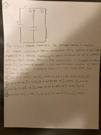
The diagram presents an electrical circuit featuring a DC voltage source, a switch, and two branches.
- The left branch includes a series combination of a resistor and an ideal capacitor.
- The right branch includes a series combination of a resistor and an ideal inductor.
The currents flowing through these branches are labeled as \(I_1\) for the capacitive branch and \(I_2\) for the inductive branch.
**Text Explanation:**
The circuit above contains a DC voltage source, a switch, a branch containing a series combination of a resistor and an ideal capacitor, and a branch containing a series combination of a resistor and an ideal inductor. How do the currents (\(I_1\) in the capacitive branch and \(I_2\) in the inductive branch) in the two branches compare as soon as the switch is closed and then at a long time after the switch is closed?
**Options:**
- **(a)** At \(t = 0\) → \(I_1 = \text{max}\), \(I_2 = \text{max}\) + at \(t = \infty\) → \(I_1 = 0\), \(I_2 = 0\)
- **(b)** At \(t = 0\) → \(I_1 = 0\), \(I_2 = 0\) + at \(t = \infty\) → \(I_1 = \text{max}\), \(I_2 = \text{max}\)
- **(c)** At \(t = 0\) → \(I_1 = 0\), \(I_2 = \text{max}\), + at \(t = \infty\) → \(I_1 = \text{max}\), \(I_2 = 0\)
- **(d)** At \(t = 0\) → \(I_1 = \text{max}\), \(I_2 = 0\), + at \(t = \infty\) → \(I_1 = 0\), \(I_2 = \text{max}\)
Expert Solution
This question has been solved!
Explore an expertly crafted, step-by-step solution for a thorough understanding of key concepts.
Step by stepSolved in 2 steps with 2 images

Knowledge Booster
Similar questions
- di Dü D. The following values are given for a three-phase transformer: 30, 35 MVA, 154 kV/10.5 kV, 50 Hz, i 0.6%, UN 13%, Po-28 kW, P=170 kW, Yd11 connected, ONAF cooling system Find and draw the equivalent circuit parameters of the transformer in terms of both real and unit values. Calculate the efficiency of the transformer when operated at 70% load with an inductive power factor of 0.9. Relative voltage drop and secondary voltage when the transformer is operated at 70% load with an inductive power factor of 0.9. Calculate both unit value and rms real value. Calculate at what load ratio the maximum efficiency is achieved in this transformer with an inductive power factor of 0.9. Calculate the maximum efficiency mentioned in part (d).arrow_forward2) A series RLC cireuit consists of a 150-2 resistor, a 21-µF capacitor and a 460-mH inductor, connected in series with a 120- V, 60-Hz power supply. a) What is the phase angle between the current and the applied voltage? b) Which reaches its maximum earlier, the current or the voltage? eearrow_forward22) A capa citor wired in an a inductor are an series in an LC os cil ator. The period of the is 4j tu lly charged, but there What 0scilla tion Initially at t =0, the capaci tor s is curren t in the no cir cuit is the earliest time af ter the maximum ! lsec) t-0 +hat Current isarrow_forward