Structural Analysis
6th Edition
ISBN: 9781337630931
Author: KASSIMALI, Aslam.
Publisher: Cengage,
expand_more
expand_more
format_list_bulleted
Question

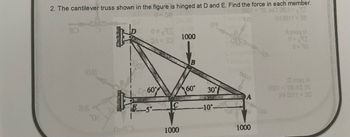
Transcribed Image Text:2. The cantilever truss shown in the figure is hinged at D and E. Find the force in each member.
0001 = '06 800 38,0-
0-83
0=x23
QA=30
60%
C
1000
6.6
1000
B
60°
DE
30%
-10°-
Compres
0001
A
1000
48
21 2011=38
0=√73
0=30
Omog A
0001 = 108 m2 30
Weert = 90
Expert Solution
This question has been solved!
Explore an expertly crafted, step-by-step solution for a thorough understanding of key concepts.
Step by stepSolved in 4 steps with 3 images

Knowledge Booster
Learn more about
Need a deep-dive on the concept behind this application? Look no further. Learn more about this topic, civil-engineering and related others by exploring similar questions and additional content below.Similar questions
- Use the substitute member to make a complete analysis of the complex truss shown. b d 3m 25kN 4 m f e1.5 m a. 2 at 4 m = 8 marrow_forwardDetermine the forces in members EF and GI of the truss shown.arrow_forwardDetermine the forces in all the members of the complex truss shown below. State if the members are in tension or compression. Hint: Substitute member AD with one placed between E and C.arrow_forward
- How do i solve the attached trusses/civil engineering problem?arrow_forwardCompute for the force in each member of the truss in figure 1.arrow_forwardQ2; For the truss shown in the force Fr and the forces in members BF, BG and BA, when the force in CD is 3.75 KN Tension ? Figure (2), determine FiD 5 KN 3m loky 3M KN B 10 +4marrow_forward
- The portion of truss shown represents the upper part of a power transmission line tower. The 2.7 kN force is 60° from the vertical. For the given loading, determine all zero force members. a. Use the Method of Section to find the forces in members BC, EH and EJ; b. Use the Method of Joints to find the forces in members BD and DE.arrow_forwardDetermine the force in each member of the truss. State if the members are in tension or compression. F E 12 kN 8 kN 3 m 45° V24 kN 4 m 4 m 4 marrow_forwardFind 5 internal forces of the truss members also Find all zero force member.arrow_forward
- The truss shown is used to support the floor deck. The uniform load on the deck is 2.5 k/ft. This load is transferred from the deck to the floor beams, which rest on the top joints of the truss. Determine the force in each member of the truss, and state if the members are in tension or compression. Assume all members are pin connected.arrow_forwardDetermine the force in each member of the complex truss shown in Fig. below. Assume joints B, F, and D are on the same horizontal line. State whether the members are in tension or compression 4 ft 3 ft B 45° 5 k F 45% -8 ft- D Earrow_forwarddetermine the zero-force members in the trusses shown below.P = 120 N, S = 150 Narrow_forward
arrow_back_ios
SEE MORE QUESTIONS
arrow_forward_ios
Recommended textbooks for you

 Structural Analysis (10th Edition)Civil EngineeringISBN:9780134610672Author:Russell C. HibbelerPublisher:PEARSON
 Principles of Foundation Engineering (MindTap Cou...Civil EngineeringISBN:9781337705028Author:Braja M. Das, Nagaratnam SivakuganPublisher:Cengage Learning
 Fundamentals of Structural AnalysisCivil EngineeringISBN:9780073398006Author:Kenneth M. Leet Emeritus, Chia-Ming Uang, Joel LanningPublisher:McGraw-Hill Education
 Traffic and Highway EngineeringCivil EngineeringISBN:9781305156241Author:Garber, Nicholas J.Publisher:Cengage Learning


Structural Analysis (10th Edition)
Civil Engineering
ISBN:9780134610672
Author:Russell C. Hibbeler
Publisher:PEARSON

Principles of Foundation Engineering (MindTap Cou...
Civil Engineering
ISBN:9781337705028
Author:Braja M. Das, Nagaratnam Sivakugan
Publisher:Cengage Learning

Fundamentals of Structural Analysis
Civil Engineering
ISBN:9780073398006
Author:Kenneth M. Leet Emeritus, Chia-Ming Uang, Joel Lanning
Publisher:McGraw-Hill Education


Traffic and Highway Engineering
Civil Engineering
ISBN:9781305156241
Author:Garber, Nicholas J.
Publisher:Cengage Learning