
Elements Of Electromagnetics
7th Edition
ISBN: 9780190698614
Author: Sadiku, Matthew N. O.
Publisher: Oxford University Press
expand_more
expand_more
format_list_bulleted
Related questions
Concept explainers
Question
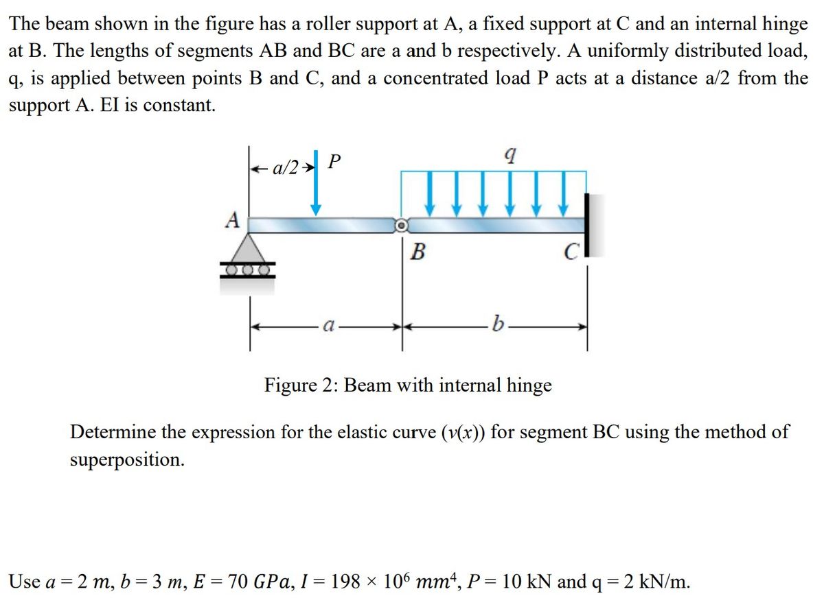

Transcribed Image Text:The beam shown in the figure has a roller support at A, a fixed support at C and an internal hinge
at B. The lengths of segments AB and BC are a and b respectively. A uniformly distributed load,
q, is applied between points B and C, and a concentrated load P acts at a distance a/2 from the
support A. EI is constant.
a/2 P
por quity
A
B
Figure 2: Beam with internal hinge
Determine the expression for the elastic curve (v(x)) for segment BC using the method of
superposition.
Use a = 2 m, b = 3 m, E = 70 GPa, I = 198 × 106 mm4, P = 10 kN and q = 2 kN/m.
Expert Solution
This question has been solved!
Explore an expertly crafted, step-by-step solution for a thorough understanding of key concepts.

This is a popular solution

Trending nowThis is a popular solution!

Step by stepSolved in 3 steps with 3 images

Knowledge Booster


Learn more about
Need a deep-dive on the concept behind this application? Look no further. Learn more about this topic, mechanical-engineering and related others by exploring similar questions and additional content below.Similar questions
- Please don't provide handwritten solution .....arrow_forwardThe figure shows an aluminum beam OB with rectangular cross section, pinned to the ground at one end and supported by a round steel rod with hooks formed on the ends. A load is applied as shown. Use superposition to determine the vertical deflection at point A. 2 in 6 in. where F-104 lbf -in dia. F -in thick 12 in -A 12 in B The vertical deflection at point A is .0706 × 10-3 in.arrow_forwardDon't use chat gptarrow_forward
- A built-in cantilever beam with a hollow rectangular cross-section is subjected to a uniformly distributed load as shown in Figure Q1 below. Which of the following statements best describes the shear force variation along the length, in the x direction, using the sign conventions provided in lectures? Figure Q1 O a ltis constant and positive throughout the length. Ob.it is constant and negative throughout the length. Ocit begins as a negative value and increases linearly to reach a positive value of the same magnitude. Od. None of the provided answers are correct. Oelt begins with a positive constant value for half the length, then suddenly decreases to a negative value, remaining constant for the remaining length. Of. It increases linearly from zero, then continues at a constant value before decreasing linearly to reach a value of zero again. Og It begins as a positive value and decreases linearly to reach a value of zero at the end of the length of the beam.arrow_forwardNeed help please, round answers to 3 sig figsarrow_forwardThe frame shown in Figure 3.1 has internal pins at points B, C and D and is supported by a pin at point A and a roller at point E. The loading consists of two concentrated loads and a point moment, as shown in the figure. a) Calculate the support reactions at points A and E. A 6 in. B -9 -9 in. →✦9 in. →✦9 in. →| 500 lb 700 lb ←9 in. D E Figure 3.1 - Compound Frame 2 kip-in 12 in. 12 in.arrow_forward
- The snow loading near a skylight is shown below and has the following information: B1 loading is 10 kPa B4 loading is 3.8 kPa Beam span is 9 m Dis 18.5 m B4 83 Find the loading over B2 and B3. Round to 4 signifigant digits. B2 load Number B3 load Number kPa kPa B2 B1arrow_forwardFigure Q2 shows an 11 m long steel beam AC of uniform cross-section, simply supported at left end A and roller supported at location B. A uniformly distributed load of 40 kN/m is applied on the part AB of the beam together with a concentrated load of 20 kN at the end C. 20 kN 40 kN/m В. 8 m 3 marrow_forward> Next question You can retry this question below A triangular distributed load of max intensity w-490 N/m acts on beam AB. The beam is supported by a pin at A and member CD, which is connected by pins at C and D respectively. Determine the reaction forces at A and C. Enter your answers in Cartesian components. Assume the masses of both beam AB and member CD are negligible. cc 030 BY NC SA 2016 Eric Davishahl Variable Value 6.6 m a b C D 11.88 m 4.95 m Values for dimensions on the figure are given in the following table. Note the figure may not be to scale. The reaction at A is A = -11268.69 N. The reaction at Cis C= 11268.69 N. 20 Submit Question Jump to Answer X2-3923.92 B X2+ -8451.52 H X Xarrow_forward
arrow_back_ios
arrow_forward_ios
Recommended textbooks for you
- Elements Of ElectromagneticsMechanical EngineeringISBN:9780190698614Author:Sadiku, Matthew N. O.Publisher:Oxford University Press
 Mechanics of Materials (10th Edition)Mechanical EngineeringISBN:9780134319650Author:Russell C. HibbelerPublisher:PEARSON
 Thermodynamics: An Engineering ApproachMechanical EngineeringISBN:9781259822674Author:Yunus A. Cengel Dr., Michael A. BolesPublisher:McGraw-Hill Education
  Control Systems EngineeringMechanical EngineeringISBN:9781118170519Author:Norman S. NisePublisher:WILEY
 Mechanics of Materials (MindTap Course List)Mechanical EngineeringISBN:9781337093347Author:Barry J. Goodno, James M. GerePublisher:Cengage Learning
 Engineering Mechanics: StaticsMechanical EngineeringISBN:9781118807330Author:James L. Meriam, L. G. Kraige, J. N. BoltonPublisher:WILEY
Elements Of Electromagnetics
Mechanical Engineering
ISBN:9780190698614
Author:Sadiku, Matthew N. O.
Publisher:Oxford University Press
Mechanics of Materials (10th Edition)
Mechanical Engineering
ISBN:9780134319650
Author:Russell C. Hibbeler
Publisher:PEARSON
Thermodynamics: An Engineering Approach
Mechanical Engineering
ISBN:9781259822674
Author:Yunus A. Cengel Dr., Michael A. Boles
Publisher:McGraw-Hill Education
Control Systems Engineering
Mechanical Engineering
ISBN:9781118170519
Author:Norman S. Nise
Publisher:WILEY
Mechanics of Materials (MindTap Course List)
Mechanical Engineering
ISBN:9781337093347
Author:Barry J. Goodno, James M. Gere
Publisher:Cengage Learning
Engineering Mechanics: Statics
Mechanical Engineering
ISBN:9781118807330
Author:James L. Meriam, L. G. Kraige, J. N. Bolton
Publisher:WILEY