Concept explainers
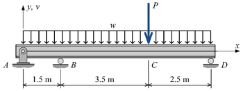
The beam shown in Figure Q.2 consists of a W610 × 140 structural steel wide-flange shape [E = 200 GPa; I = 1120 × 106 mm4]. If w = 52 kN/m and P = 129 kN , determine:
a) Calculate the value of the deflection at point B due to uniformly distributed load w in the form:
v_B=(answer)/(EI)
b) Calculate the value of the deflection at point B due to concentrated load P in the form:
v_B=(answer)/(EI)
c)Calculate the vertical reaction at support B. When sketching FBD, assume the positive direction of all reactions in the positive direction of y axis.
d) Calculate the vertical reaction at support D.
e) Calculate the vertical reaction at support A.
f) Find the maximum bending moment in the beam.
g) Calculate the magnitude of the maximum bending stress in the beam

Step by stepSolved in 10 steps with 12 images

- Nd,Vd,Md,Ne,Ve,Mearrow_forwardA beam of rectangular cross-section 40 x 20 mm is loaded with tensile force 1000 N as shown in figure. A B BO Calculate the shear stress on oblique plane at 0 = 45° A 0.625 MPa C 0.31 MPa F D 1.25 MPaarrow_forwardThe beam shown in the figure is subjected to a moment of M = 50 kN.m. Determine the bending stress at point A and B.arrow_forward
- Upvote will be given. Please write the solutions legibly. Solve in 2 decimal places. 10 KN 10 KN 25 KN/m 20 KN/m 1m Im B Tm C Tm D 1 E 15 m FIGURE 1 A. What is the maximum internal shear force of the beam in FIGURE 1? B. What is the maximum internal bending moment of the beam in FIGURE 1?arrow_forwardThe pin-jointed frame in the figure below has members of cross-sectional area A=1200mm² and young modulus of elasticity of 200.5 GPa. If a vertical concentrated load of 1200KN (downward) and horizontal force of 800KN (to the right) are applied at Point D. Determine: a. The vertical displacement at D in mm. b. The horizontal displacement at D in mm. c. The stress of AD due to actual loads in kN. d. The stress of AB due to horizontal unit load. e. The stress of BD due to vertical unit load. 4m B 3m C 3m F Earrow_forwardConsider the continuous beam as shown in figure below: RA 9,- 2 6 (m) R₂ What will be the magnitude of slope at B? H₂ 6 (m) Rearrow_forward
- Question Three The three-bar truss ABC shown in the figure part a has a span L = 3 m and is constructed of steel pipes having cross-sectional area A = 3900 mm² and modulus of elasticity E = 200 GPa. Identical loads P act both vertically and horizontally at joint C, as shown. (a) If P=475 kN, what is the horizontal displacement of joint B? (b) What is the maximum permissible load value Pmax if the displacement of joint B is limited to 1.5 mm? P A 45° 45° B L (a)arrow_forward1. The figure below shows a two simply supported beams and cross each other at 90 degrees on midspan. The length of the beams are both 3 meters long. At their cross-over point, both beams carries the load of 135KN. Use nominal dimensions and neglect the weight of the beam. Upper beam = 250mm x 300mm. Lower beam = 300mm x 300mm. a. compute the load carried by the lower beam. b. compute the bending stress of both upper and lower beam.arrow_forwardI need the answer as soon as possiblearrow_forward
- A pin-jointed 2-D truss is loaded with a vertical load of 10 kN as shown in figure. The crosssectional area of the horizontal member is 150 mm² and cross-section areas of the members AC and BC are 200 mm² each. Modulus of elasticity of the truss material is 200 kN/mm². The magnitude of horizontal displacement (in mm, round off to two decimal places) of joint Cis A -6m 10 KN 5 m 4.5 marrow_forwardSolve the problem by the moment-area method. The beam has constant flexural rigidity EI. A simple beam AB supports two concentrated loads P at the positions shown in the figure. B C 4. 4 A support C at the midpoint of the beam is positioned at distance d below the beam before the loads are applied. Assuming that d = 12 mm, L = 5.4 m, E = 200 GPa, and I = 193 x 10° mm, calculate the magnitude of the loads P (in kN) so that the beam just touches the support at C. 163.87 x kNarrow_forwardFor the structure and loading shown below, find the lateral deflection at the top. Use E = 29,000 ksi and I = 250 in4 for all members. Note that in frames, we neglect axial deformation, so you can calculate the deflection at either of the upper corners; the answer will be the same. %3D 20 8K 10!arrow_forward

 Structural Analysis (10th Edition)Civil EngineeringISBN:9780134610672Author:Russell C. HibbelerPublisher:PEARSON
 Principles of Foundation Engineering (MindTap Cou...Civil EngineeringISBN:9781337705028Author:Braja M. Das, Nagaratnam SivakuganPublisher:Cengage Learning
 Fundamentals of Structural AnalysisCivil EngineeringISBN:9780073398006Author:Kenneth M. Leet Emeritus, Chia-Ming Uang, Joel LanningPublisher:McGraw-Hill Education
 Traffic and Highway EngineeringCivil EngineeringISBN:9781305156241Author:Garber, Nicholas J.Publisher:Cengage Learning


