Elements Of Electromagnetics
7th Edition
ISBN: 9780190698614
Author: Sadiku, Matthew N. O.
Publisher: Oxford University Press
expand_more
expand_more
format_list_bulleted
Concept explainers
Question

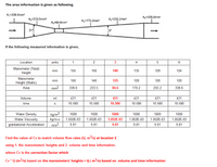
Transcribed Image Text:## Transcription of Technical Diagram and Table Data
### Diagram Explanation
The diagram illustrates a fluid flow section with varying cross-sectional areas. Starting from the left, the areas and their measurements are as follows:
- **A1 = 338.6 mm²**
- **A2 = 233.5 mm²**
- **A3 = 84.6 mm²**
- **A4 = 170.2 mm²**
- **A5 = 255.2 mm²**
- **A6 = 338.6 mm²**
An 8° angle marks the transition between the narrowest and broader sections. This setup is likely used for analyzing changes in flow rate and pressure through different sections.
### Data Table
The table provides measured information at different locations along the setup. The critical data points are bolded.
#### Table Header
- **Location** (numbered 1 to 6)
- **Units** for each measurement
#### Measurements
1. **Manometer (Total) Height** in mm:
- Locations 1 to 6: 155, 150, **140**, 135, 129, 124
2. **Manometer Height (Static)** in mm:
- Locations 1 to 6: 150, 140, **125**, 120, 120, 120
3. **Area** in mm²:
- Locations 1 to 6: 338.6, 233.5, **84.6**, 170.2, 255.2, 338.6
4. **Volume** in ml:
- All locations: 431
5. **Time** in seconds:
- All locations: **10.580**
6. **Water Density** in kg/m³:
- All locations: 1000
7. **Water Viscosity** in kg/m·s:
- All locations: 1.052E-03
8. **Gravitational Acceleration** in m/s²:
- All locations: **9.81**
### Task Instruction
**Find the value of Cv to match volume flow rates (Q, m³/s) at location 3** using:
1. The manometers' heights
2. Volume and time information
**Where Cv is the correction factor,** the equation is:
\[ \text{Cv} \times Q (\text{m
Expert Solution
This question has been solved!
Explore an expertly crafted, step-by-step solution for a thorough understanding of key concepts.
This is a popular solution
Trending nowThis is a popular solution!
Step by stepSolved in 2 steps

Knowledge Booster
Learn more about
Need a deep-dive on the concept behind this application? Look no further. Learn more about this topic, mechanical-engineering and related others by exploring similar questions and additional content below.Similar questions
Recommended textbooks for you
 Elements Of ElectromagneticsMechanical EngineeringISBN:9780190698614Author:Sadiku, Matthew N. O.Publisher:Oxford University Press
 Mechanics of Materials (10th Edition)Mechanical EngineeringISBN:9780134319650Author:Russell C. HibbelerPublisher:PEARSON
 Thermodynamics: An Engineering ApproachMechanical EngineeringISBN:9781259822674Author:Yunus A. Cengel Dr., Michael A. BolesPublisher:McGraw-Hill Education
 Control Systems EngineeringMechanical EngineeringISBN:9781118170519Author:Norman S. NisePublisher:WILEY
 Mechanics of Materials (MindTap Course List)Mechanical EngineeringISBN:9781337093347Author:Barry J. Goodno, James M. GerePublisher:Cengage Learning
 Engineering Mechanics: StaticsMechanical EngineeringISBN:9781118807330Author:James L. Meriam, L. G. Kraige, J. N. BoltonPublisher:WILEY

Elements Of Electromagnetics
Mechanical Engineering
ISBN:9780190698614
Author:Sadiku, Matthew N. O.
Publisher:Oxford University Press

Mechanics of Materials (10th Edition)
Mechanical Engineering
ISBN:9780134319650
Author:Russell C. Hibbeler
Publisher:PEARSON

Thermodynamics: An Engineering Approach
Mechanical Engineering
ISBN:9781259822674
Author:Yunus A. Cengel Dr., Michael A. Boles
Publisher:McGraw-Hill Education

Control Systems Engineering
Mechanical Engineering
ISBN:9781118170519
Author:Norman S. Nise
Publisher:WILEY

Mechanics of Materials (MindTap Course List)
Mechanical Engineering
ISBN:9781337093347
Author:Barry J. Goodno, James M. Gere
Publisher:Cengage Learning

Engineering Mechanics: Statics
Mechanical Engineering
ISBN:9781118807330
Author:James L. Meriam, L. G. Kraige, J. N. Bolton
Publisher:WILEY