Structural Analysis
6th Edition
ISBN: 9781337630931
Author: KASSIMALI, Aslam.
Publisher: Cengage,
expand_more
expand_more
format_list_bulleted
Question

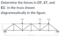
Transcribed Image Text:Determine the forces in DF, EF, and
EG in the truss shown
diagrammatically in the figure.
40 kN
40 kN
40 kN
DI
B
2m
E
G
K
6 @ 3m = 18m-
Expert Solution
This question has been solved!
Explore an expertly crafted, step-by-step solution for a thorough understanding of key concepts.
This is a popular solution
Trending nowThis is a popular solution!
Step by stepSolved in 2 steps with 2 images

Knowledge Booster
Similar questions
- Determine the force in each member of the truss as shown in the figure.arrow_forwardAnswer as negative value if the force is in compression and positive if it is in 2.47 2.77 3.17 -2.87 2.87 -2.47 -3.17arrow_forwardThe length of BC and CD are the same, calculate the force in each member of the struss.arrow_forward
- Determine the force in members CD and CE of the truss shown belowarrow_forwardAnalyze the trusses shown .EA= constant 12 kN 10 kN D 2 m 2 m B 2 m G. 3 m 3 m 3 marrow_forwardAnalyze the truss structures below (note: determine all reactions and member forces; for member forces, specify tension or compression).arrow_forward
- number 6 theoryarrow_forwardExample 2 Determine the force in members bd, cd & ce as shown in truss by section method? Find reactions at b & a → Σ Fx = 0 +→ 4m 4 4m C 300 kN 4marrow_forwardDetermine the force in each member of the truss shown. 1o ere100 kN Iou 100 kN b 35 kN- 3 m 7 m B 4 m 3 m 3 m 4 marrow_forward
- 1. Given: A structure shown below Find: (1) Determine the magnitudes and locations of the two distributed loadings. In other words, determine the magnitude and location of the loading between A and C, and those of the loading between D and B. (2) For the member DEB, (a) take the moment at B and find the reaction at E and (b) then find By by either Fy= 0, or EMp = 0. (Recall that support conditions at B and E are rollers, so there are no reactions in x-direction.) (3) For the whole structure, 3 unknown forces and moment at A (Ax, Ay and Ma) are the only unknowns. Determine those 3 unknowns at A. 900 N/m 900 N/m B A C D 2E - 3 m 3 m - 4 m - 3 m3 m-arrow_forwardIn the truss shown in Figure. Determine the force member at DE. * 400 kN 800 kN 6 m 3 m F 3 m 6 m E 6 m 200 kN 200 kN 1440 KN tension O 1440 KN compression 200 KN tension None of the above O 200 KN compressionarrow_forwardUse the method of joints to calculate the forces in all the members of the truss shown in Figure 2 below. 20KN 30⁰ C Rc B RB 60⁰ A 5m Figure 2arrow_forward
arrow_back_ios
SEE MORE QUESTIONS
arrow_forward_ios
Recommended textbooks for you

 Structural Analysis (10th Edition)Civil EngineeringISBN:9780134610672Author:Russell C. HibbelerPublisher:PEARSON
 Principles of Foundation Engineering (MindTap Cou...Civil EngineeringISBN:9781337705028Author:Braja M. Das, Nagaratnam SivakuganPublisher:Cengage Learning
 Fundamentals of Structural AnalysisCivil EngineeringISBN:9780073398006Author:Kenneth M. Leet Emeritus, Chia-Ming Uang, Joel LanningPublisher:McGraw-Hill Education
 Traffic and Highway EngineeringCivil EngineeringISBN:9781305156241Author:Garber, Nicholas J.Publisher:Cengage Learning


Structural Analysis (10th Edition)
Civil Engineering
ISBN:9780134610672
Author:Russell C. Hibbeler
Publisher:PEARSON

Principles of Foundation Engineering (MindTap Cou...
Civil Engineering
ISBN:9781337705028
Author:Braja M. Das, Nagaratnam Sivakugan
Publisher:Cengage Learning

Fundamentals of Structural Analysis
Civil Engineering
ISBN:9780073398006
Author:Kenneth M. Leet Emeritus, Chia-Ming Uang, Joel Lanning
Publisher:McGraw-Hill Education


Traffic and Highway Engineering
Civil Engineering
ISBN:9781305156241
Author:Garber, Nicholas J.
Publisher:Cengage Learning