Introductory Circuit Analysis (13th Edition)
13th Edition
ISBN: 9780133923605
Author: Robert L. Boylestad
Publisher: PEARSON
expand_more
expand_more
format_list_bulleted
Question

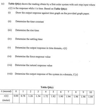
Transcribed Image Text:(c)
Table Q4(c) shows the reading obtain by a first order system with unit step input where
c(t) is the response while t is time. Based on Table Q4(c):
(i)
Draw the output response against time graph on the provided graph paper.
(ii)
(iii) Determine the rise time
(iv)
Determine the time constant
(v)
Determine the settling time
Determine the output response in time domain, c(t)
(vi) Determine the force response value
(vii) Determine the natural response value
(viii) Determine the output response of the system in s-domain, C(s)
t (second) 0 1
c(t)
(meter)
2
3
0.00 0.78 1.26 1.54
Table Q4(c)
4
1.72
5
1.82
6 7
8
9
1.90 1.94 1.96 1.98
10
1.99
Expert Solution
This question has been solved!
Explore an expertly crafted, step-by-step solution for a thorough understanding of key concepts.
Step by stepSolved in 4 steps with 4 images

Knowledge Booster
Learn more about
Need a deep-dive on the concept behind this application? Look no further. Learn more about this topic, electrical-engineering and related others by exploring similar questions and additional content below.Similar questions
- Design a capacitive transducer to be able to measure the displacementof a rotating element in a machine. Sketch the diagram and specifywhich parameters will let you measure the displacement.arrow_forwardThe buck converter with resistive load has the input voltage of 30[V], the output voltage of 10[V] (constant), and the switching frequency of 40 [kHz]. If the output average power is 25[W], then determine the size of the inductor such that the minimum inductor current is 25 % of the average inductor current.arrow_forwardFor the circuit below define the fields described in the rows by matching them to a letter given for an equation or a value in Figure 1. v. () (1+ jwRC) v. () ¯(1 + J»RC) (a) (b) R Zero Infinite (c) (d) V (1+ jeRC) (f) (e) Unity (e) (h) Figure1. Output voltage in terms of input voltage Choose... + The expression for the ratio of input voltage to output voltage Choose... + as frequency tends towards zero Gain as frequency tends Choose... + towards zero Voltage Gain Choose... + Gain as frequency tends towards infinity Choose... + Choose... +arrow_forward
- I need answer as quick as possible.arrow_forwardII. QUESTIONS: 1. What is the phase shift of the input and output waveform?arrow_forwardThe serial data-input waveform (Data in) and data-select inputs (S0 and S1) are shown in Figure Determine the data-output waveforms from D0 through D3.arrow_forward
- i need the answer quicklyarrow_forward0.02 (e) The responses in the figure below are for a unit step change in the disturbance with just P-control. One of the responses used a controller gain of Ke = 5 and the other used a controller gain of Ke = 8. Match the controller gains with the responses. Response to a Unit Step Change in Disturbance With P-Control 0.07 Response 1 --- Response 2 0.06 0.05 H 2 0.04H S 0.03 0.01 5 10 15 20 Time (min) (f) The responses in the figure below are for a unit step change in set point with a PI controller. The gain is the same for both responses but one response uses an integral time of ti = 1 min and the other uses an integral time of t = 2 min. Match the integral times for the PI controllers with the responses. r Response to a Unit Step Change in Set Point With Pl-Control 1. Respanse 1 --- Respanse 2 1.4 1.2 0.8 O 0.6- 0.4 0.2H 10 15 20 Time (min) (h) Determine the missing information for the sensor system in the following table. The output for the sensor system is a mA signal. Range Zero…arrow_forwardPlease I want to solve the question Q1&Q2&Q4arrow_forward
- Why do think the output voltage ?? resembles the input sinusoid?arrow_forwardW/ explaination 4.) Find Peak time (Tp) (oloos) percent overshoot, CTs) setting time, Rise Time CTR) of -4 +10 s²+55+C4+10) b.) Draw the time Responsearrow_forwardSOLVE CAREFULLY!! Please Write Clearly and Box the final Answer Hint : Enter your answer to the 3rd nearest decimal place in seconds.arrow_forward
arrow_back_ios
SEE MORE QUESTIONS
arrow_forward_ios
Recommended textbooks for you
 Introductory Circuit Analysis (13th Edition)Electrical EngineeringISBN:9780133923605Author:Robert L. BoylestadPublisher:PEARSON
 Delmar's Standard Textbook Of ElectricityElectrical EngineeringISBN:9781337900348Author:Stephen L. HermanPublisher:Cengage Learning
 Programmable Logic ControllersElectrical EngineeringISBN:9780073373843Author:Frank D. PetruzellaPublisher:McGraw-Hill Education
 Fundamentals of Electric CircuitsElectrical EngineeringISBN:9780078028229Author:Charles K Alexander, Matthew SadikuPublisher:McGraw-Hill Education
 Electric Circuits. (11th Edition)Electrical EngineeringISBN:9780134746968Author:James W. Nilsson, Susan RiedelPublisher:PEARSON
 Engineering ElectromagneticsElectrical EngineeringISBN:9780078028151Author:Hayt, William H. (william Hart), Jr, BUCK, John A.Publisher:Mcgraw-hill Education,

Introductory Circuit Analysis (13th Edition)
Electrical Engineering
ISBN:9780133923605
Author:Robert L. Boylestad
Publisher:PEARSON

Delmar's Standard Textbook Of Electricity
Electrical Engineering
ISBN:9781337900348
Author:Stephen L. Herman
Publisher:Cengage Learning

Programmable Logic Controllers
Electrical Engineering
ISBN:9780073373843
Author:Frank D. Petruzella
Publisher:McGraw-Hill Education

Fundamentals of Electric Circuits
Electrical Engineering
ISBN:9780078028229
Author:Charles K Alexander, Matthew Sadiku
Publisher:McGraw-Hill Education

Electric Circuits. (11th Edition)
Electrical Engineering
ISBN:9780134746968
Author:James W. Nilsson, Susan Riedel
Publisher:PEARSON

Engineering Electromagnetics
Electrical Engineering
ISBN:9780078028151
Author:Hayt, William H. (william Hart), Jr, BUCK, John A.
Publisher:Mcgraw-hill Education,